Blitzortung
Setting up my station for the blitzortung.org measuring network
The Blitzortung project makes it possible to detect lightning strikes with an accuracy of a few meters. This is made possible by a large community, which builds, installs and operates the respective measuring stations. The recorded data is available in real time. It is not only of interest from a scientific point of view, but can even protect human lives during outdoor activities. In the next section, I would like to describe my station in Uelzen, which I installed in 2016 - one of the thousands of stations worldwide.
The positioning takes place with the so-called TOA (time of arrival) method. An electromagnetic interference generated by the lightning strike is evaluated, time-stamped and sent to a central server. The server combines identical signals from different receivers and determines the exact position using the signal propagation time. At least 6 stations are required to calculate the position. Since all receivers receive their reference clock via the 1pps output of the GPS module, this creates a reference time stamp in the microsecond range.
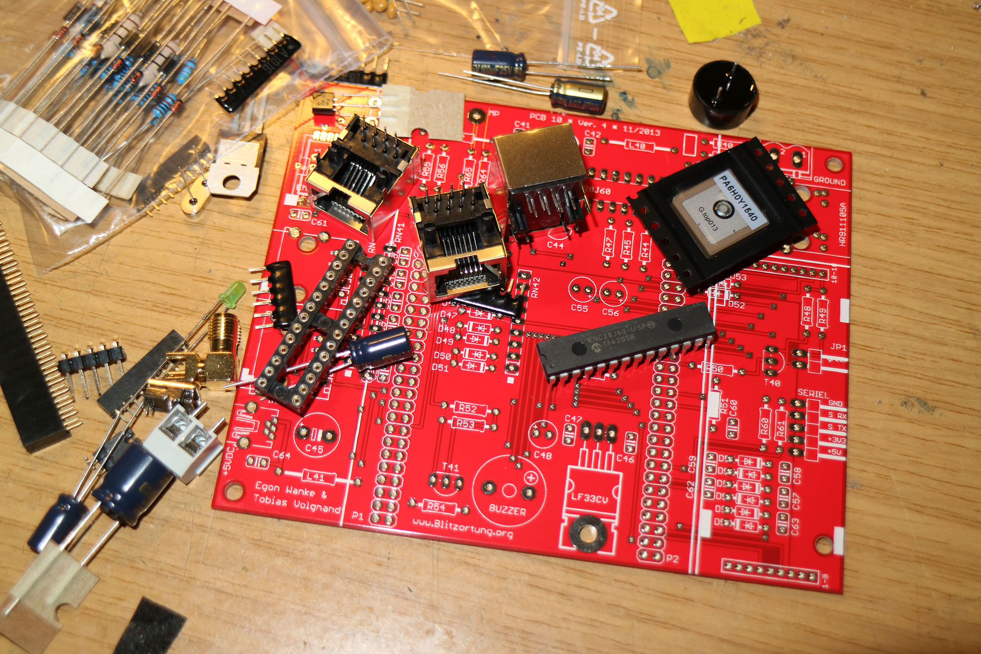
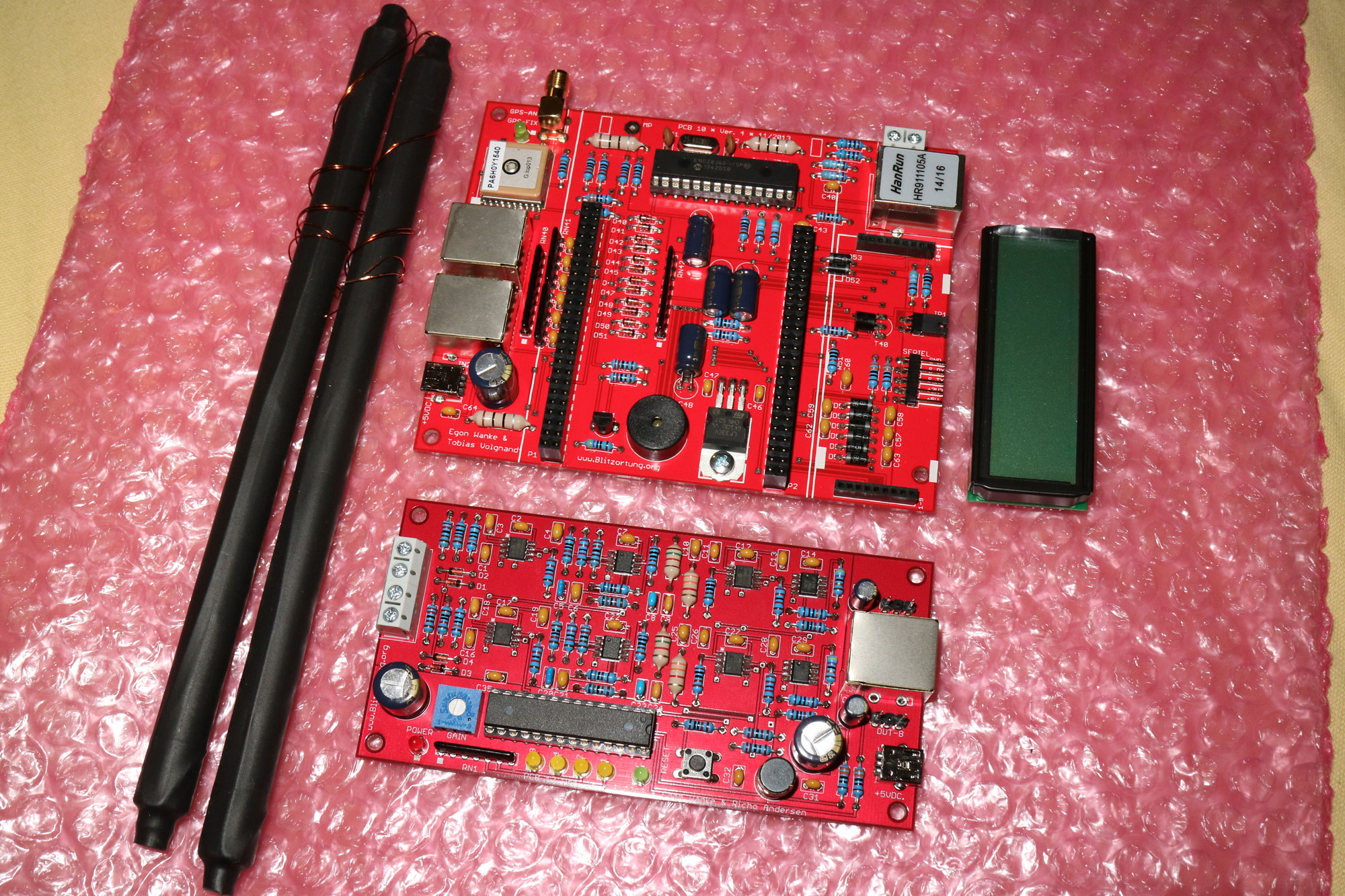
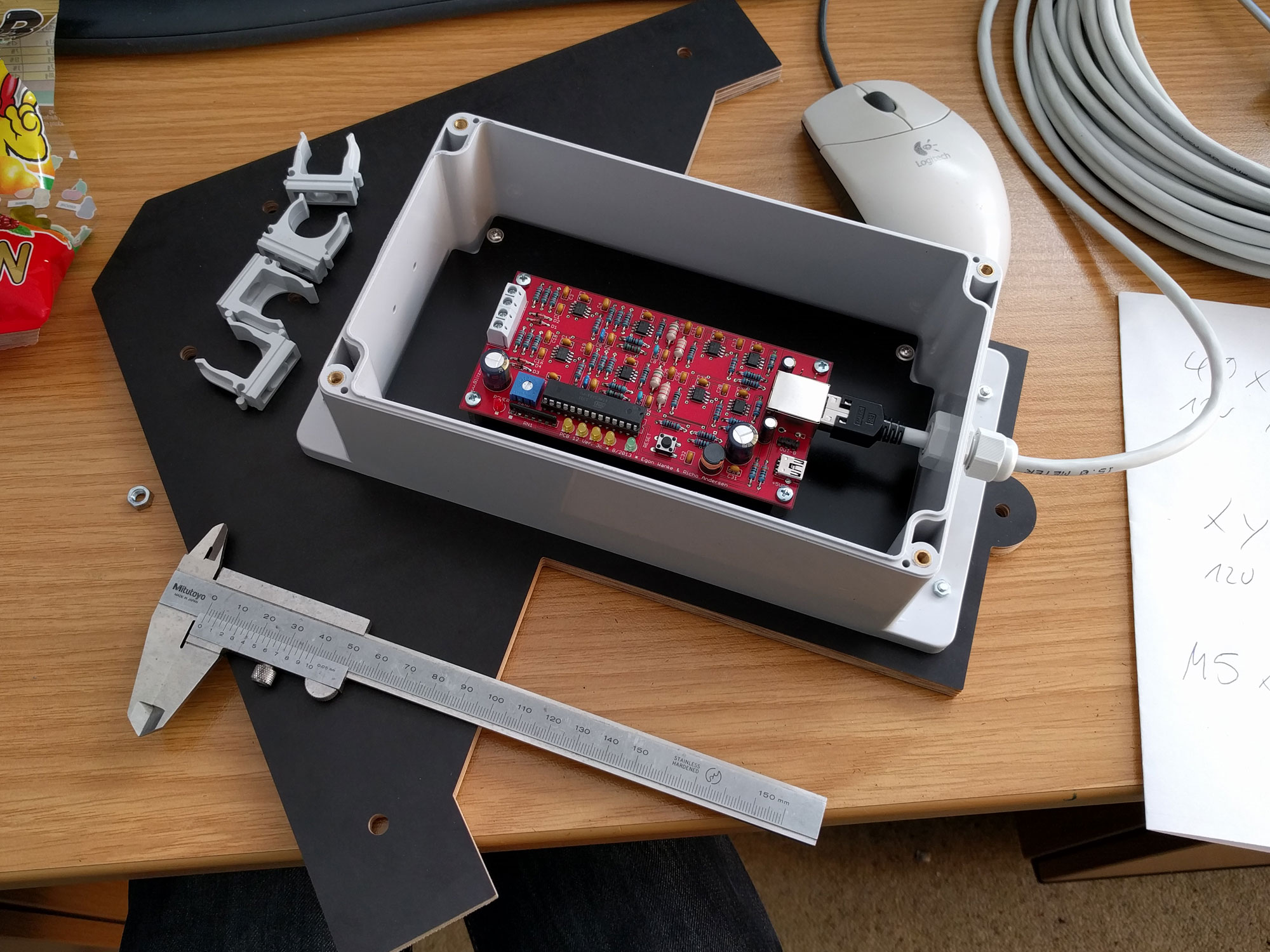
The price for the kit is around 200€. The RED system shown here required time-consuming assembly of the boards by hand. In the meantime it was replaced by the system Blue. This comes mostly pre-assembled with SMD components.
Different types of antennas are possible. The E-field antenna consists of a vertically mounted wire. It receives the electric field. H-field antennas, in contrast, use the magnetic field. You may select between ferrite rods or various loop antennas. E- or H-field antennas use different preamplifiers, so be sure to decide before ordering. I have chosen the widely used ferrite antennas. These can be ordered already wound. With the 20cm long ferrite rods the maximum detection distance can be up to 1000km during the day and 2000km at night, depending on the conditions.
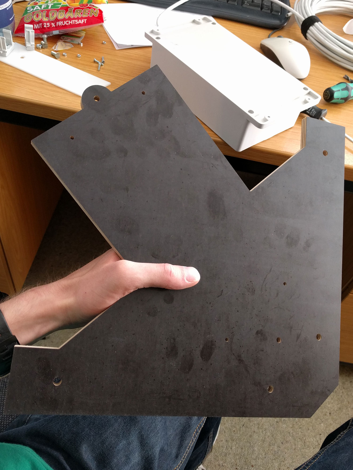
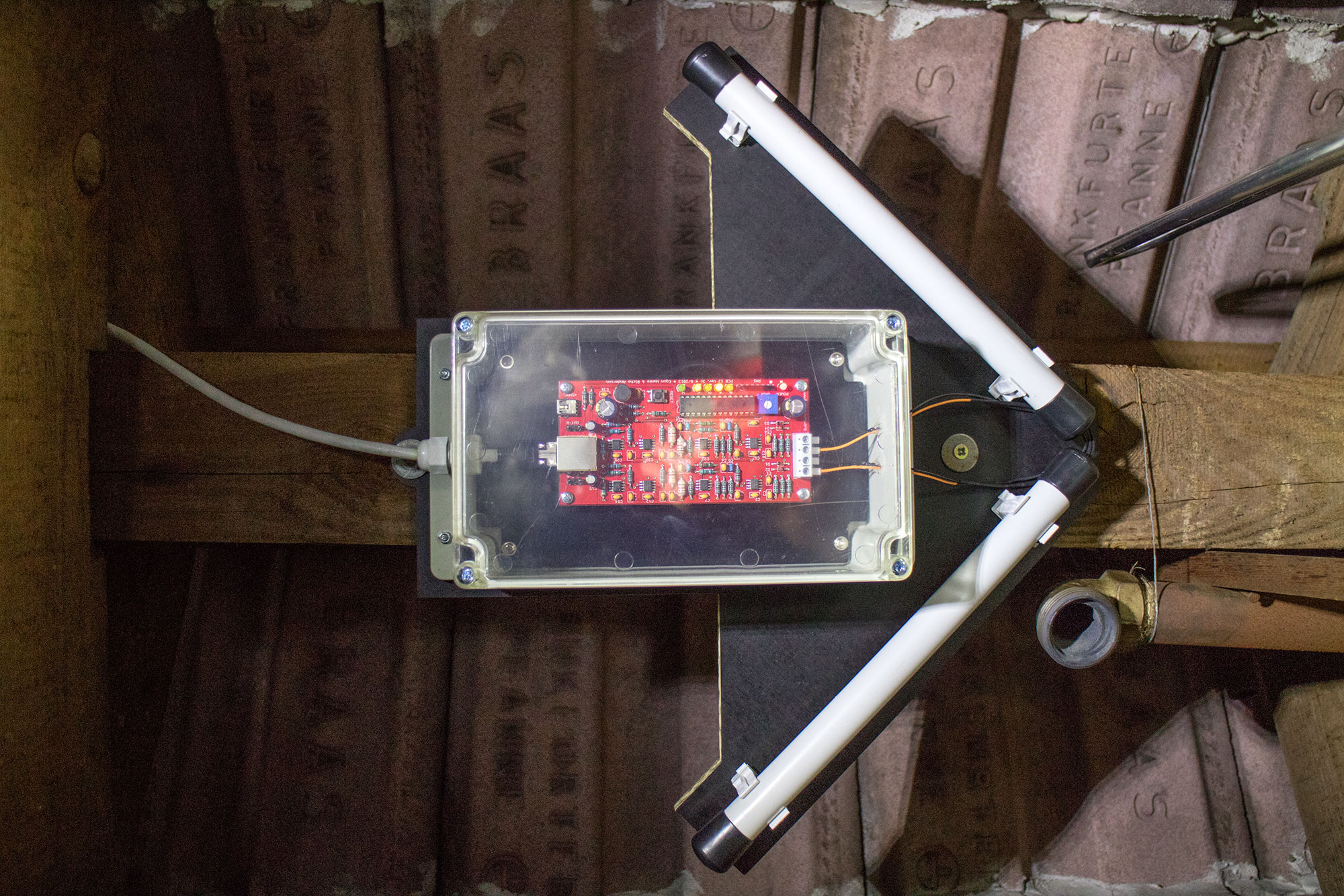
In order to receive signals from all directions, the ferrite rods must be positioned at a 90 degree angle to each other. They are mounted horizontally. A special alignment according to the cardinal direction is not necessary. I CNC milled a proper mount out of film faced plywood. The antennas are fitted into EN20 installation tubes, padded with foam, fixed with suitable clamps and closed at the end with chair leg caps.
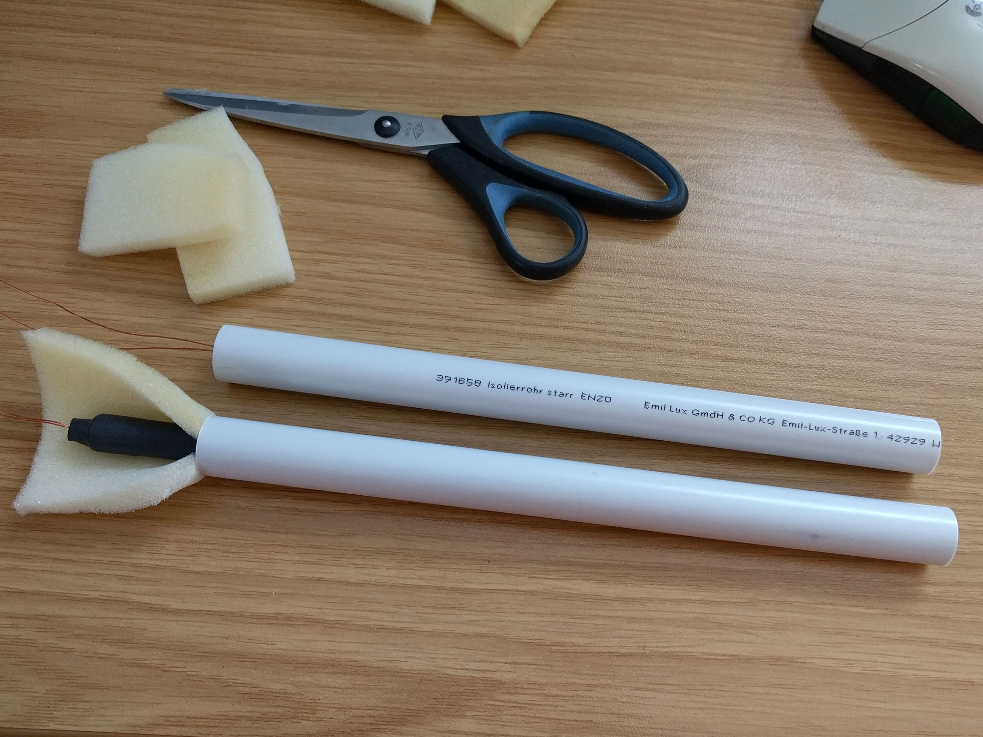
A circuit board with the appropriate preamplifier is located directly at the antenna. It is connected to the controller with a simple RJ45 network cable. I use Kerpen Megaline E5-70 cables with Hirose connectors. To compensate interferences, the two antennas are mounted in a 45 degree angle to the preamplifier.

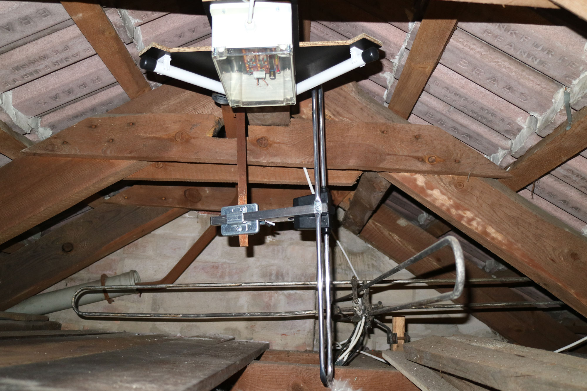
Antennas and preamplifiers are mounted below the roof. This eliminates the need for the otherwise required lightning protection devices if the spacing is sufficient. Due to the low frequencies, no loss of range is to be expected with indoor installation. The GPS antenna, however, needs a clear view of the sky. Window glass is not a problem as long as it is not vaporized with metal.
For an optimal GPS signal I use a Garmin GA38 antenna. This one is made for the marine sector and is thus waterproof and has a very strong reception. It is currently installed under the roof, but will later be mounted on a boom on the antenna mast. There is a LMR240 low-loss coax cable which leads from the attic to the controller.

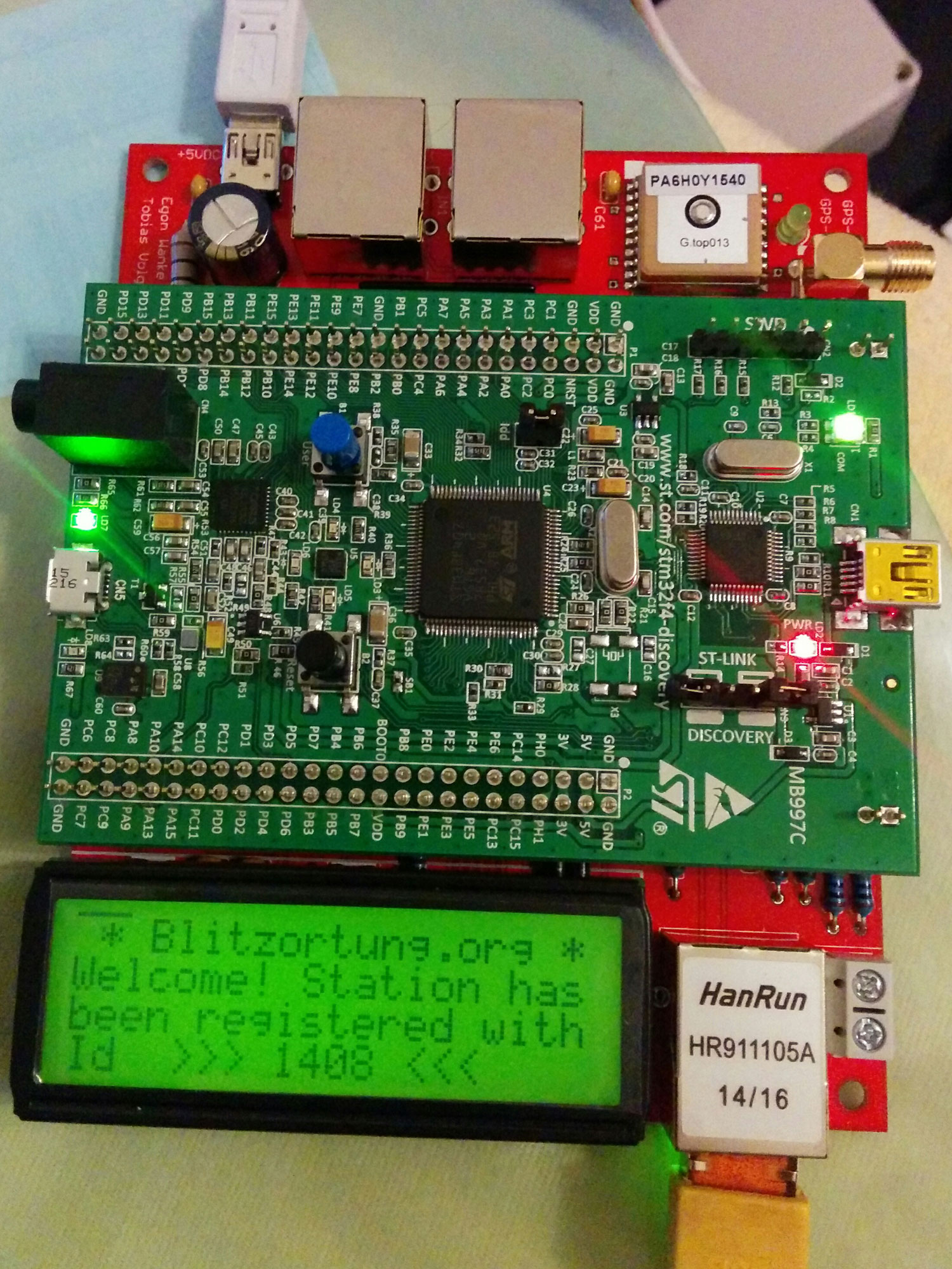
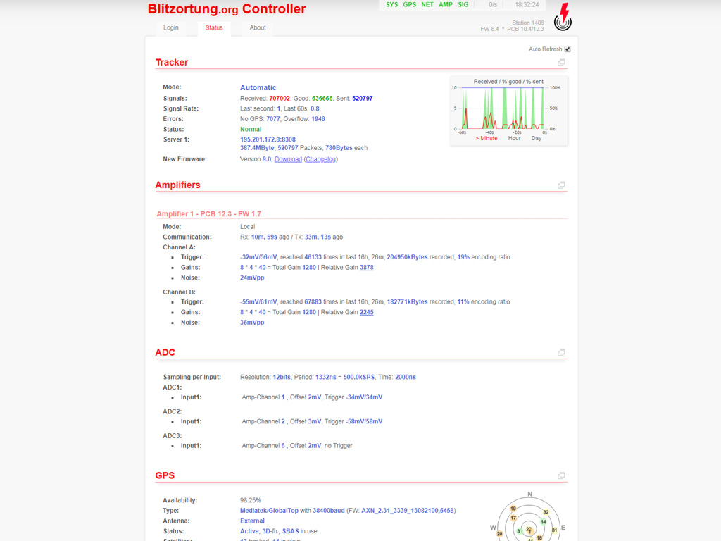
In a space at the bottom of the roof pitch, the network distribution and the controller for lightning detection are located, to which VLF and GPS antenna signals as well as LAN and 5V power supply are connected. The System RED board connects peripherals like GPS receiver, network chip and LC display to a STM32 F4 discovery board. System Blue consists of only one board. The firmware has to be flashed once via USB, and can then be updated from any computer in the network via the web interface if necessary. After registration on the server, the station works completely automatically. If necessary, fine adjustments can be made via web browser.
Current real-time data and statistics can be viewed by anyone without registration at lightningmaps.org. Station operators also have access to the complete data archive for non-commercial purposes. Software and hardware are closed source.
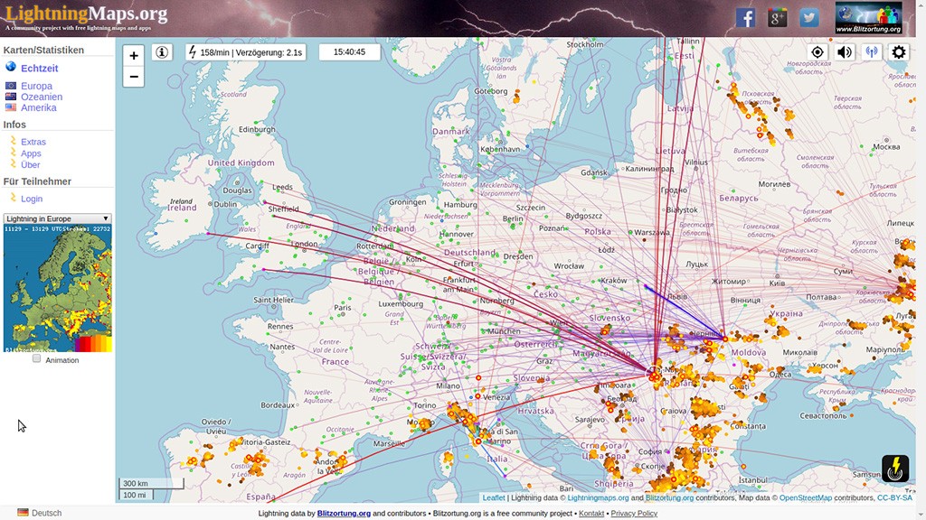
If you want to operate your own station, you should take a look at the live map. The locations of the stations can be displayed there. A distance of 50 to 300km is reasonable between individual stations. I have linked further information worth reading below.