ESP8266 MiLight Hub
Smart home gateway for MiLight bulbs

In search of affordable lighting options for the garden, I came across the components of the Asian manufacturer MiLight. The product range does not only include bulbs in common sockets such as E27 or GU10, but there are also waterproof RGB spots with IP65 certification for outdoor use.
To control color, brightness and other functions, a wireless remote control or the appropriate WLAN gateway with smartphone app can be used. The lamps can be programmed to several remote controls. If the gateway is used, it converts the control commands to the same, unencrypted 2.4GHz protocol, which is also used by the remote control. The advantage of a central gateway compared to systems in which each light bulb itself is integrated into the WLAN, is the lower power consumption and the simpler configuration. Access data for the network is only stored in the gateway.
The functionality of the original WLAN gateway is largely limited on usage with the app. Although there is a UDP protocol, it is hardly documented and may deviate depending on the software version of the gateway.
The 2.4GHz wireless protocol of the remote, however, was already reverse-engineered by Henryk Plötz and is accordingly well documented. The following project is built on his work.
A do-it-yourself WLAN gateway
Upon further research, I found the project ESP8266 MiLight Hub by Chris Mullins on GitHub. The ESP8266 MiLight Hub replaces the manufacturer\'s gateway. The remote control via WLAN can be done from any smartphone, tablet or PC by using a web browser. The installation of an app is not necessary. For integration into own Smart Home projects there is a REST API as well as an MQTT Client. A test on the breadboard convinced me.
So all I needed was a fitting board in an outdoor housing for this project, which I designed within the next few days.
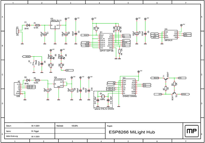
The circuit is based on the minimal necessary components as they are found on every ESP8266 development board.
Pull-Up and Down resistors on the GPIO pins 0, 2 and 15 cause the ESP to boot from its internal flash memory. For programming a CH340 USB to serial converter is installed. The two transistors secure the data lines RTS and DTR against each other, which are used during flashing to reset and start the bootloader. An LT1117 linear regulator ensures power supply via USB during programming. When the board is mounted in the case, the socket is not accessible.
The actual power supply is implemented by a efficient buck converter module LME78_03-1.0. The input voltage at the screw terminal may vary between 6 and 36 volts.
Self-resetting fuses in front of both voltage regulators ensure safety in case of a short circuit.
As additional peripherals there's the necessary NRF24L01 2.4GHz radio module as well as LEDs for displaying the operating status and a reset button.
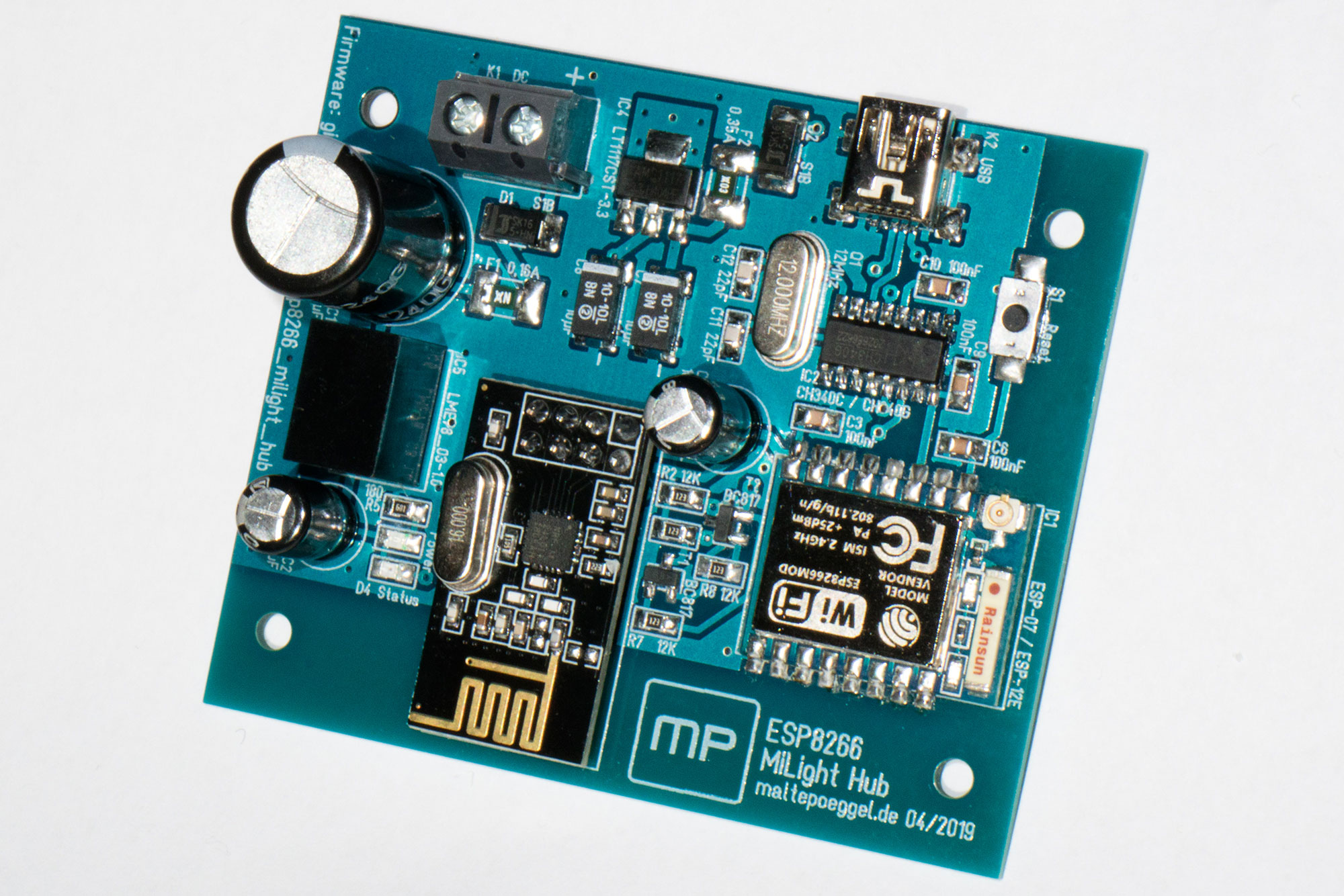
The double-sided PCB is equipped with SMD components. Resistors and capacitors in 0805 size can easily be soldered by hand with a little practice.
Now the firmware has to be transferred to the ESP8266. You can either use precompiled binaries or compile them yourself. To translate the source code ourselves, we need Git and PlatformIO. The latest version of the firmware is currently found in Branch 1.10.8. We clone the repository, change to the folder and then call the build system PlatformIO. The parameters for this must be adapted depending on the module used (ESP07 or ESP12) and the virtual COM port on which the USB to serial converter is connected.
cd esp8266_milight_hub
platformio run -t upload -e esp07 --upload-port /dev/ttyUSB0
If everything worked well, the MiLight Hub can now be found via a configuration network with the name "ESP_xxxxxx" and password "milightHub" and integrated into the own network via the configuration interface on http://192.168.4.1/. The assigned IP address can be viewed in the WLAN router.
The web interface can now be accessed from any device in the home network via http://<ip_of_the_esp>/
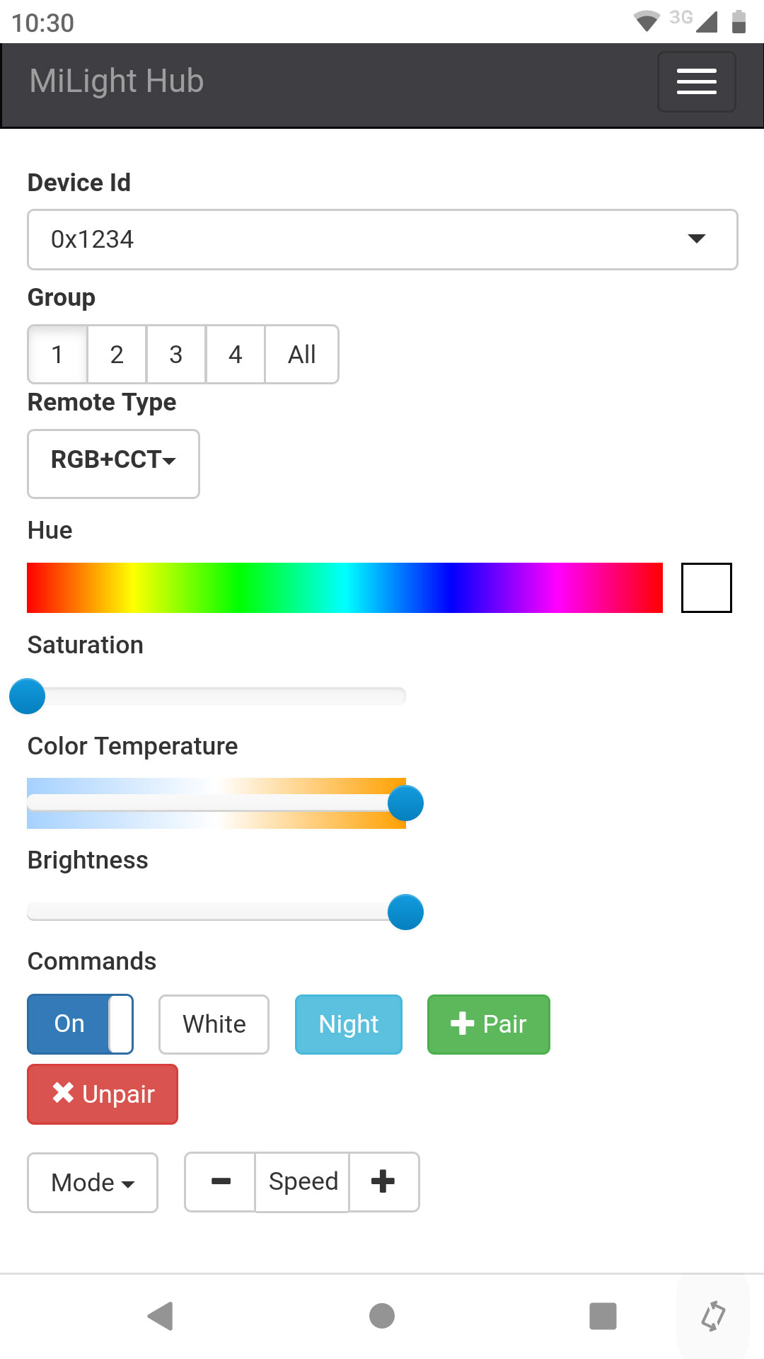
After that, a device ID has to be created. It corresponds to the fixed, random code of an original remote control. MiLight devices can be programmed within the first 2 seconds after connecting to the power supply. Simply screw in / switch on the lamp and quickly press the "Pair" button in the web interface. Per device ID, four groups are possible. Any number of devices can be programmed to these groups. The programming can be done quite comfortably for every single bulb one by one.
Conclusion
The bulbs are inexpensive and seem well-made. The self-built MiLight Hub offers a lot of control options directly by using any web browser and without installing an app. Due to the free choice of Device ID, the gateway is no longer limited to just four groups. In addition, there are well documented interfaces for integration into your own Smart Home projects.
Links
- PCB at OSH Park
- ESP8266 MiLight Hub Software (GitHub)
- Chris Mullins blog, developer of the MiLight Hub Firmware