IoT Geiger Counter
Geiger-Müller Counter with WLAN / LoRa connection
Recently, I received a question about which Geiger counter is best suited as a radiation monitor at a weather station. I have been running a uRadmonitor Kit1 for this purpose for several years. However, this kit is not very flexible due to the LAN port, and the measured values can only be stored in a separate, local database via workarounds.
After further research on the Internet, I could not find a suitable design that would meet the requirements of a stationary device as the base of a wireless weather station. A new project idea was born.
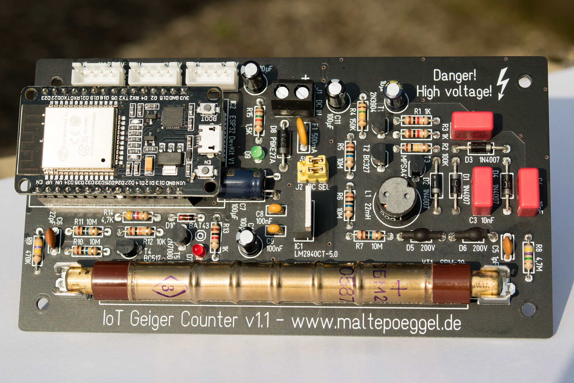
Some years ago I had already built a prototype of a circuit with SBM-20 counter tube from the Mikrocontroller.net forum, have a look at the YouTube video. It was made by the user "kolisson". The advantage of this circuit is the use of standard components and the very low quiescent current consumption. The construction is realized as a self oscillating boost switching regulator followed by a Villard multiplier circuit. The output voltage is adjusted via Zener diodes.
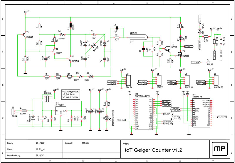
Circuit description
The transistors T2 and T3 constitute the self-blocking oscillator, which charges the storage choke L1. With the cascade connected afterwards, the voltage induced by the coil is thus multiplied. As soon as the voltage at C4 reaches the anode voltage of 400V set by the Zener diodes, they switch off the oscillating circuit via transistor T1. The anode resistor R8 limits the current through the counter tube. The 1pF capacitor C5 connected in parallel is a suggestion to improve the plateau characteristics, but may be omitted as well.
The 10nF capacitors C2, C3, C4 in the cascade are specified at 630V. In tests, the WIMA MKP10 series has proven to be optimal due to its low losses. The ceramic capacitors C5 and C6 should have a dielectric strength of 500V. In addition, the choice of Zener diodes is critical. Again, leakage current plays a significant role. Depending on the type, the high voltage is more or less precisely regulated. I have chosen the Zener diodes BZT03C200. Since these seem to have a photoelectric effect in the glass package, it is recommended to cover the Zener diodes with heat shrink tubing before soldering them in. This is not necessary for the alternatives in plastic packages (e.g. 2EZ200D5) mentioned in the parts list. To check the anode voltage, a very high impedance analog voltmeter (e.g. Unigor 3n with 31.6kOhm/V in the 1kV range) should be used. Digital voltmeters usually have an impedance of 10MOhm in all ranges, which causes the high voltage to drop by a few hundred volts. Some more info can be found in this Twitter thread.
The SBM-20 counter tube was made in the Soviet Union and is easy to obtain from remaining stocks. Alternatively, the J305βγ (107mm length) from China can be used. Both detect beta and gamma rays with comparable sensitivity. If the gas in the counter tube is ionized, the high voltage is discharged via the voltage divider consisting of R9, R10 and R11. C6 extends the resulting pulse. This is amplified by the Darlington transistor T4, switches the field-effect transistor T5, and finally causes the light-emitting diode D7 to flash.
A digital processing of the pulses is performed either by an ESP32 (WLAN) or a Moteino R6 (LoRa). The conversion to 3.3V logic level is done by clever wiring of the Schottky diode D10. The 3.3V flow through this diode and through R14 as soon as the field effect transistor T5 switches to ground by a pulse. This means that the output is low-active. The input pins of both microcontrollers are chosen to allow internal timer circuits to be used as counters. But more on this later.
Either a DC-DC module or a low drop voltage regulator (IC1) is provided for the power supply. This will generate the necessary 5V from an input voltage of 6 to 26V. If a regulated 5V supply is already present, the voltage regulator can be bridged with the jumper J2. The self-resetting fuse F1 and the TVS diode D8 protect against reverse polarity and overvoltage.
The JST sockets J3 to J6 are used for I2C and UART interfaces, each with a 3.3V or 5V power supply. Additional sensors can be connected to these ports. A signal level of 3.3V should not be exceeded on all data lines.
Assembly
When assembling the board, start with the smallest / thinnest components (resistors, diodes, etc). Special care should be taken with the field effect transistor T5: It is sensitive to electrostatic discharges. After assembly, the bottom of the board must be cleaned of flux residues with isopropyl alcohol or methylated spirit, as these may be conductive. If you wish, you can additionally coat the high-voltage part with insulating lacquer (e.g. Plastik 70 made by CRC Kontaktchemie).
Enclosure and mounting
The dimensions of the board are designed for installation in an IP65 housing such as G368 / G258. Identical cases with the outer dimensions 160x80x55mm are offered by different manufacturers. If you need more space, you can alternatively use the housing G369 / G265 with an overall height of 85mm. All cables should be inserted via sealed PG glands. Before installing the board, the two spacers located under the sockets must be trimmed using a drill or side cutter. Although the enclosure is waterproof, it is preferable to install it in a protected location. It is also recommended to install a pressure compensation element, as otherwise changes in temperature can cause moisture to be pulled into the housing. For safety, a small packet of desiccant (silica gel) can also be taped into the housing.
Using the ESP32 with WLAN
The open-source firmware ESPHome is used as software for the ESP32. With this firmware various sensors can be integrated and processed without any programming skills required. The configuration of the firmware is done via YAML files.
ESPHome automatically uses the PCNT (Pulse Counter) module of the microcontroller. I did some tests with a function generator and was amazed by the accuracy of the values returned.
If you use HomeAssistant, you can generate and transfer the firmware directly via the web interface. If you want to upload ESPHome using your own PC, you need Python 3. Under Windows this must be installed first, on Linux it is already preinstalled. The command "pip3 install esphome" on the console starts the installation of ESPHome and all additional dependencies.
As an example, the file geigercounter.yaml can now be created with an editor:
name: geigercounter
platform: ESP32
board: esp32doit-devkit-v1
wifi:
ssid: "WLAN-SSID"
password: "WLAN-Password"
i2c:
sda: 21
scl: 22
scan: false
sensor:
- platform: pulse_counter
pin: 14
name: "CPM"
id: "cpm"
on_value:
then:
- component.update: radiation
update_interval: 60s
- platform: template
name: "Radiation"
id: "radiation"
state_class: "measurement"
unit_of_measurement: "uSv/h"
lambda: |-
return (id(cpm).state * 0.00570027);
accuracy_decimals: 3
update_interval: never
# Enable BME280 temperature / humidity / barometric pressure sensor
# - platform: bme280
# temperature:
# name: "Temperature"
# id: "temperature"
# oversampling: 16x
# humidity:
# name: "Humidity"
# id: "humidity"
# pressure:
# name: "Pressure"
# id: "pressure"
# address: 0x76
# update_interval: 300s
# Enable OLED display
# font:
# - file: "gfonts://Roboto"
# id: roboto
# size: 16
#
# display:
# - platform: ssd1306_i2c
# model: "SSD1306 128x64"
# address: 0x3C
# lambda: |-
# it.printf(0, 0, id(roboto), "R: %.3f uSv/h", id(radiation).state);
# it.printf(0, 16, id(roboto), "T: %.2f °C", id(temperature).state);
# it.printf(0, 32, id(roboto), "H: %.2f %%", id(humidity).state);
# it.printf(0, 48, id(roboto), "P: %.2f hPa", id(pressure).state);
web_server:
port: 80
# Enable MQTT
# mqtt:
# broker: "192.168.0.100"
# username: "MQTT-User"
# password: "MQTT-Password"
# topic_prefix: "MQTT-Topic/geigercounter"
# log_topic:
# discovery: false
# Enable Home Assistant API
# api:
# reboot_timeout: 0s
# Enable logging
logger:
ota:
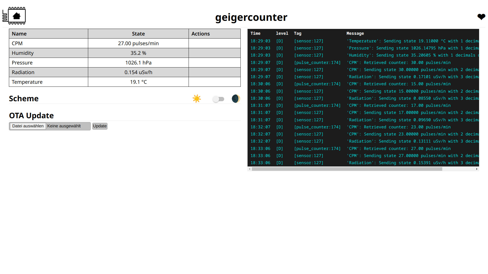
The commented out lines can be activated if a BME280 temperature, air pressure, humidity sensor or an OLED display is to be used, or if data transmission via MQTT or the Home Assistant API is desired. In any case the current values can be retrieved via the web server on the ESP32.
In order to compile the program and transfer it via USB to the ESP32, the following commands are executed in the folder where the YAML file is located:
esphome upload geigercounter.yaml
If the program has now been successfully compiled and transferred, the counter is ready for use. Using a web browser, the interface with the measured values can be viewed via the IP address assigned by the WLAN router:
Using the Moteino R6 with LoRa
LoRa radio technology can be used everywhere where no WLAN is available and a high range (1 km) to the base station (gateway) is required. The LoRaWAN implementation supports OTAA and ABP and is compatible with TheThingsNetwork and ChirpStack. A JavaScript payload decoder is also provided. Due to the relatively low power consumption of about 15mA, solar / battery operation is possible.
The processor on the Moteino is an Arduino compatible Atmel ATMega328P. For easy compilation and deployment, the PlatformIO toolchain is used. The project utilizes the popular MCCI Arduino LMIC library for LoRa. Once the network is joined, session data is stored into an SPI FRAM. Hardware timers are used to count the pulses of the GM tube and to provide a clock source for the 60-second gate time. As the transmission time in the 868MHz ISM band is limited, data is collected over a 5-minute interval and an average CPM value is calculated and sent. If a BME280 sensor is connected, temperature, humidity and barometric pressure data is also included in the transmission.
The source code and a more detailed description can be found at GitHub - IoT Geiger Counter LoRaWAN Firmware.
Visualization of the data
I personally aggregate all sensor data via MQTT (Mosquitto). It doesn't matter whether they are received directly via WLAN or via any LoRa stack. The bridge mode even allows data exchange between different MQTT servers. Telegraf stores all data in a single InfluxDB. The measured values can then be displayed in an eye-catching dashboard using Grafana.

Since a detailed explanation would go beyond the scope of this documentation, the configuration of the tools mentioned will not be discussed further here. There is enough reading material on the manufacturer's website and in various tutorials
As a possible replacement for this setup, HomeAssistant Lovelace or NodeRed Dashboard may also be used.
Conversion of the CPM values
The measured pulses per minute will differ depending on the counter tube used. To convert these into the equivalent dose, measured in Sievert, the following conversion factors are used:
- SBM-20, STS-5:
- CPM/µSV/h: 175,43
- Factor: 0.00570027
- J305βγ:
- CPM/µSV/h: 123,14709
- Factor: 0.00812037
Sources: DIY Geiger - GM Tube Info and de:arduino:radioactivity [OB121]
Within Grafana, for example, the factor can be applied directly in the SELECT statement by applying the function math(*0.00570027) to the measured CPM value out of the database.
Known issues
- Red LED lights up permanently: Defective counter tube, internal short circuit. Be careful when purchasing SBM-20 via eBay.
Errata
- Version 1.0: Prototype, unpublished
- Version 1.1: Pitch of high voltage capacitors increased to 7.5mm (Wima MKP10), various isolation distances optimized
- Version 1.2: Pitch of C7 corrected to 3.5mm, counter pulse moved from GPIO12 to GPIO14 (pullup at GPIO12 sets flash parameter in bootloader, this may cause problems)
Downloads
- Schematic (PDF)
- Bill of material (PDF)
- Layout and BOM
- Layout in Gerber format
- Circuit board at Aisler
- Circuit board at OSH Park
- LoRaWAN firmware at GitHub
There might be some boards and spare parts left from development. Drop me a message if interested.
Publications
Related projects
- g3gg0.de IoT Geiger Counter
- AATiS AS622 Geiger Counter
- MightyOhm Geiger Counter
- Ecocurious Multigeiger
- Open Source uRADMonitor KIT1
License
The PCB layout I created may be used freely for private use, but the author's name must remain on it (CC BY-NC-SA). The schematic is not subject to any restrictions.