45W LED Driver
Adjustable 700mA constant current driver for 12 volt operation
While searching for a suitable ceiling light for my bathroom, I encountered a problem: there are no low-voltage 12V LED panel lights. In Germany, DIN VDE 0100 regulates various protection zones in the bathroom. Depending on the installation area, devices and cables must meet certain protection classes, if permitted at all. Around the bathtub, only lights with safety voltage (<12V) are allowed. Even though the ceiling above 2.25m is no longer covered by this regulation, I preferred to work with low voltage here as well.
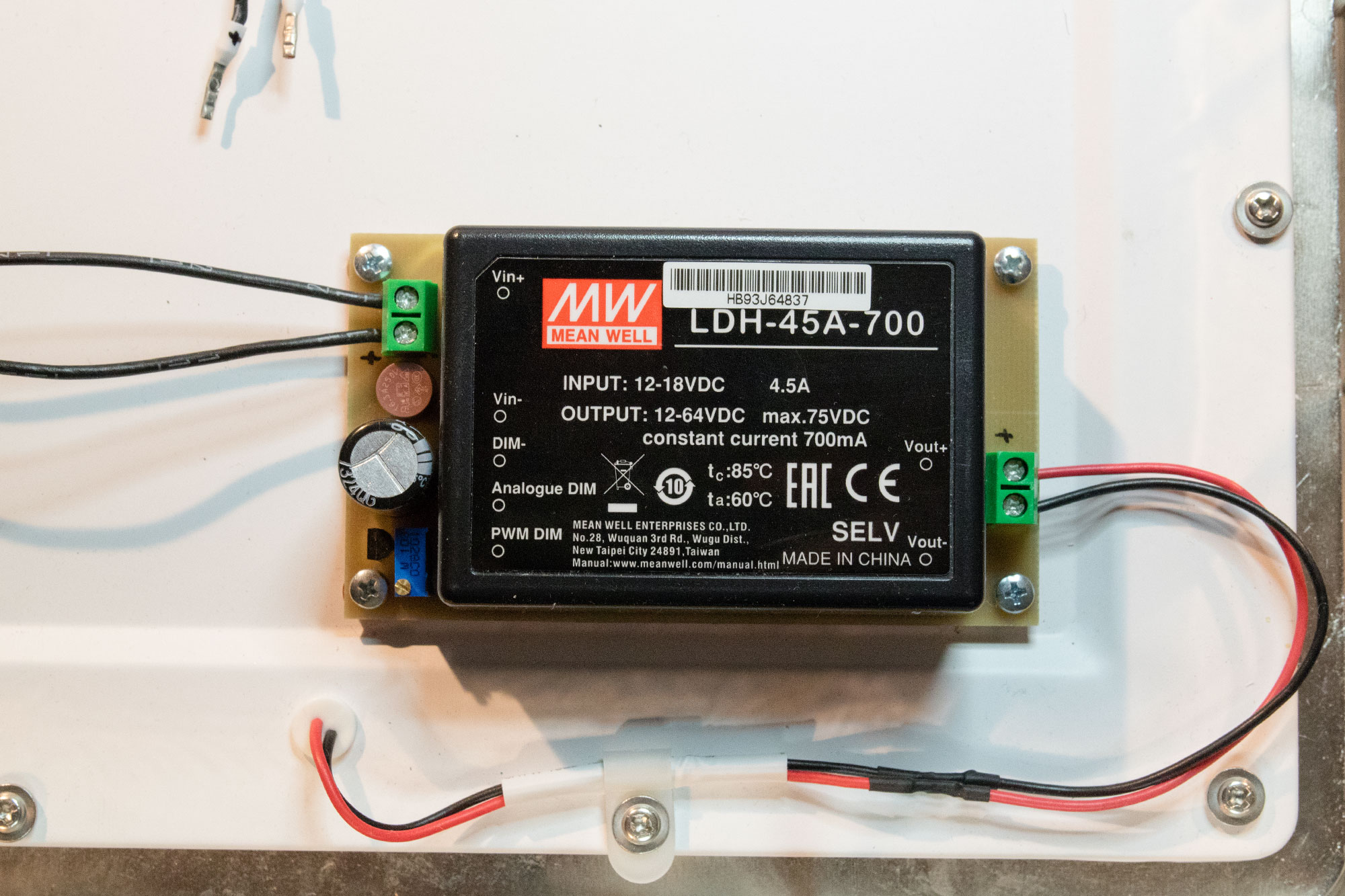
I discovered a nice LED lamp with IP44 protection, the EGLO Fueva 1 (96059). This comes with a sealed 230V LED driver with 600mA constant current. So just replace the ballast with a 12V LED driver, done? Think again. Since driver modules from Meanwell (LDH-45) with a suitable output voltage range are only available as 500 or 700mA variants. However, they are dimmable, and thus the output current can theoretically be reduced. Let's see.
The constant current driver automatically adjusts the output voltage from about 15V (equivalent to 10 watts) to 64V (at full power) depending on the number of LEDs. Dimming is done either with a PWM signal or with an analog voltage of 0.25 - 1.3 volts. A higher current at the LEDs might cause an early failure, so I want to keep the 600mA as close as possible. Thus a simple voltage divider at the dimmer input is not sufficient here, since such a circuit would be dependent on the input voltage. Therefore the reference voltage diode TL431 is used. Together with a 10-turn potentiometer, the set output current remains stable over the complete input voltage range.
Another obstacle in the datasheet is the note on page 2, which forbids a connection of the DIM pin to Vin- or Vout-. In the internet you can find some weird schematics with galvanic isolation via DCDC converter, because obviously a separate ground is necessary. Finally an explanation can be found in the DigiKey board: Vin- and DIM- are internally connected via a filter choke. If they are connected together externally, the EMI suppression is no longer given. But this also means that the ground for the rest of the circuit can simply be taken from the DIM- pin. The filter is thus connected upstream of the complete circuit.
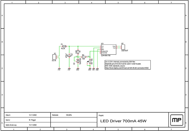
The circuit diagram is very simple. A fuse and a capacitor are connected on the input side. The 2.5 volt reference voltage is generated by TL431 from the operating voltage and DIM- as ground reference point. A voltage divider consisting of R2 and the precision potentiometer R3 halves this to 1.25 volts when the potentiometer is set in the highest position. In the lowest position, the potentiometer pulls the voltage down to 0 volts.
A small circuit board is quickly drawn and etched. As protection against moisture, the circuit board was covered with insulating varnish. It finds a place in the lamp in place of the existing ballast. Power is supplied from the existing 12V Meanwell switching power supply on the mirror cabinet. The result is a nice and uniformly illuminated bathroom.