Soldering fume extraction
Clean air during soldering thanks to the activated carbon filter
When assembling SMD boards by using soldering paste and a hotplate, I noticed that soldering fumes are released in large quantities within a short period of time. To protect my lungs, I started to look for devices for solder fume extraction. Inexpensive, commercial devices are usually operated with mains voltage and have rather mixed reviews regarding their suction power. I discovered the DIY proposal "Soldering Fume Extractor by SethBon" on Thingiverse and found it suitable. A new weekend project was found.
After ordering the fan and some small parts, I started printing. This turned out to be more difficult than expected, because in some areas too much filament was extruded. So I spent several evenings recalibrating the printer. During this process, I also updated the firmware and, out of frustration, ordered a digital caliper. A few calibrated axes and motor steps later, I was able to isolate the problem to a broken pneumatic coupling on the Bowden extruder. Everything clear for the 16-hour print of the rear half of the housing!
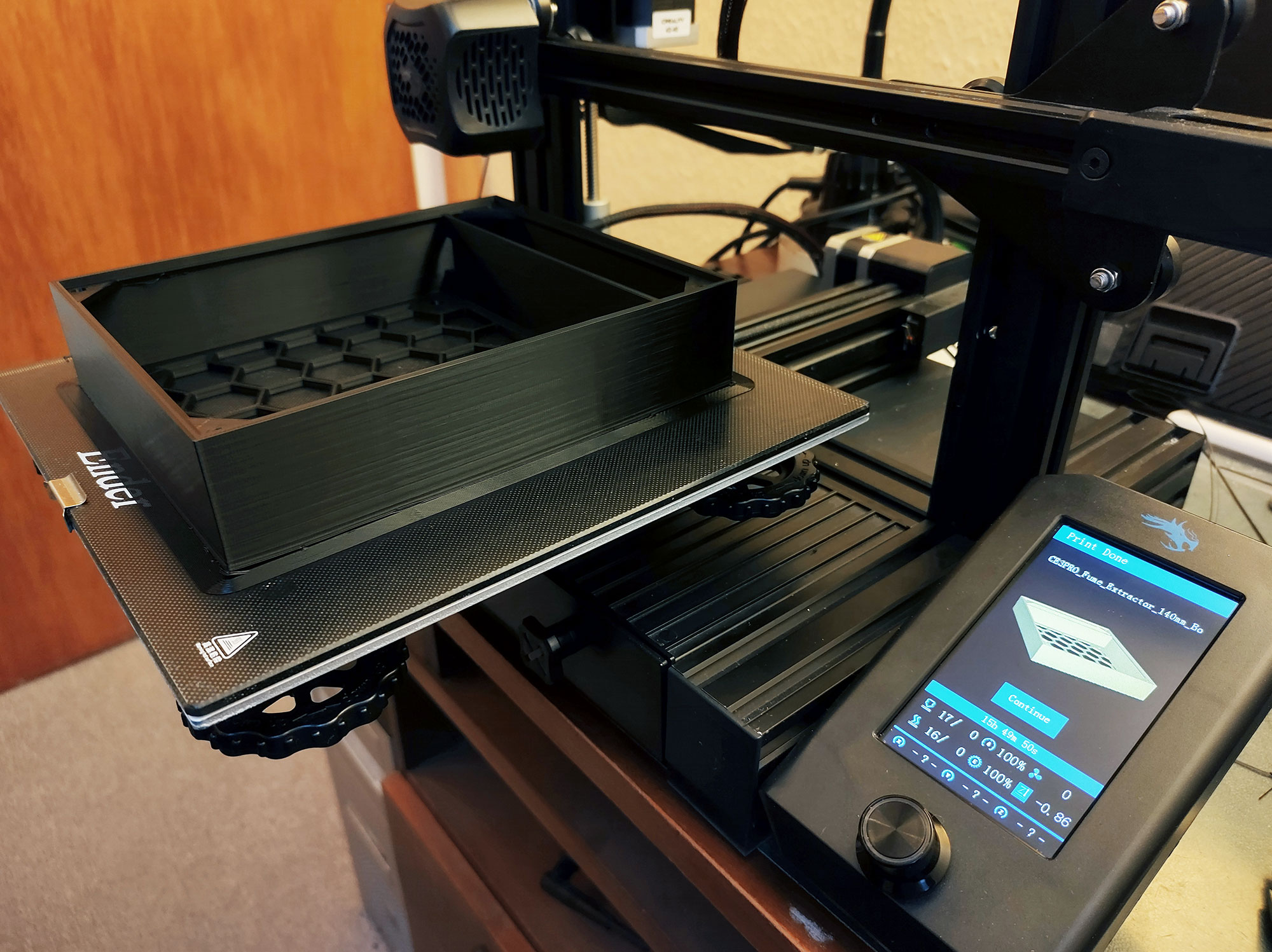
Apart from slight warping (detachment of the workpiece from the print bed), the result turned out quite well. Presumably, the room in which the printer is located was cooled down too far during the printing process on this cold February night.
Component selection
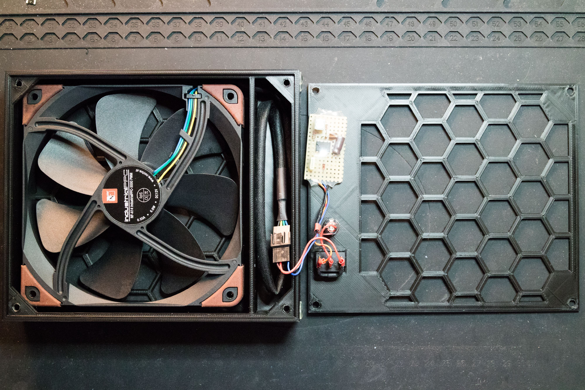
In the meantime, the ordered components had also arrived. As a fan I use the Noctua NF-A14 industrialPPC-3000 PWM. Industrial fans of this brand have a high static pressure and are thus ideally suited. Occasionally, the manufacturer offers refurbished customer returns at a lower price.
I had also purchased a two-stage switch of the type XL601-101A to enable an additional, lower speed stage. Unfortunately, the plan to make the fan run slower via a series resistor didn't work out. A quick search led me to the Noctua PWM specifications white paper. By applying a 25kHz pulse-width modulated 5V signal to the appropriate terminal of the 4-pin connector, the duty cycle determines the speed of the fan. But how to generate it? My choice went to the good old timer device NE555. A suitable circuit idea for the PWM controller, based on an astable multivibrator with fixed frequency was quickly found.
Circuit description
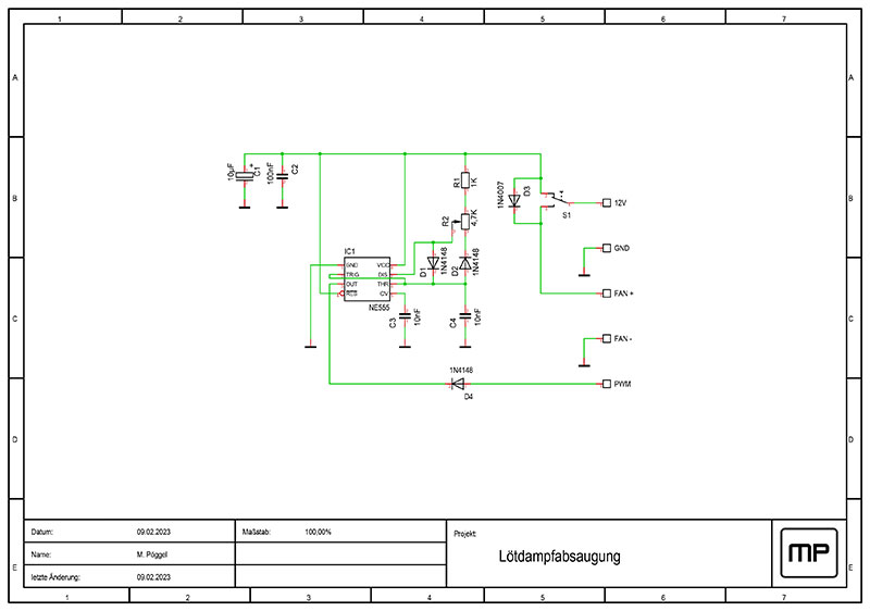
In the lower switch position at level 2, the fan is directly supplied without PWM, and thus runs at full speed. The switch also has a middle position where the power supply is interrupted. The upper switch position for level 1 supplies 12V to the PWM circuit. In this case, diode D3 simultaneously supplies the fan. The NE555 works as follows: When the operating voltage is applied, capacitor C3 charges via resistor R1, potentiometer R2, and diode D1 until it reaches 2/3 of the operating voltage. The comparator at trigger pin 2 triggers the flipflop, which activates the output and switches the discharge pin 7 to ground. There the capacitor discharges via diode D2 and potentiometer R2 until at 1/3 of the operating voltage the comparator at threshold pin 6 responds, resetting the flipflop. The wiper position of R2 determines the duty cycle, which is split between the charge and discharge branches. R1 is necessary to limit the current at the upper edge of the potentiometer when discharging. This also limits the control range a bit, but this is insignificant for our application. The capacitor C3 stabilizes the internal reference voltage. C1 and C2 are stabilizing the operating voltage of the circuit. Diode D4 acts as a level converter, since the maximum voltage at the fan's PWM pin is 5 volts. The fan has an internal pull-up resistor whose voltage flows across D4 when the output of the NE555 is turned off, thus pulling it down. If the output is active, the diode blocks and prevents the 12V output voltage from being applied to the PWM pin of the fan. A voltage divider would be unsuitable here, as it would also pull down the pin when the PWM circuit is not powered. So the fan would simply not run in level 2. The transistor in the output stage of the NE555 does not switch through without supply voltage.
Construction
The circuit is built up on a piece of breadboard and finds place in the lower part of the case. The included fan screws are used to mount the fan.
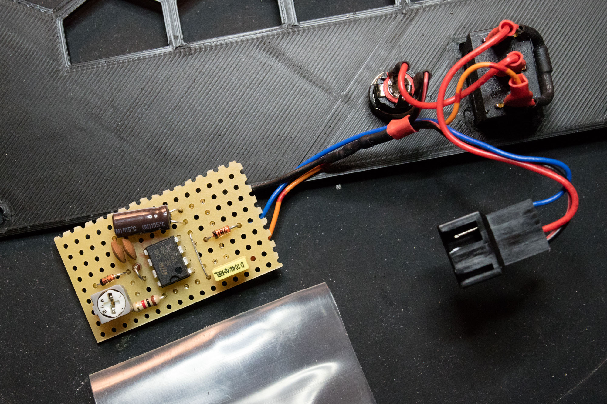
To insulate the circuit board, I use heat shrink tubing. The diode D3 is installed directly at the switch. The DC jack "HEBL 25" is available at Reichelt Elektronik. The 4-pin connector is available as computer accessory. Everything is wired together according to the circuit diagram.
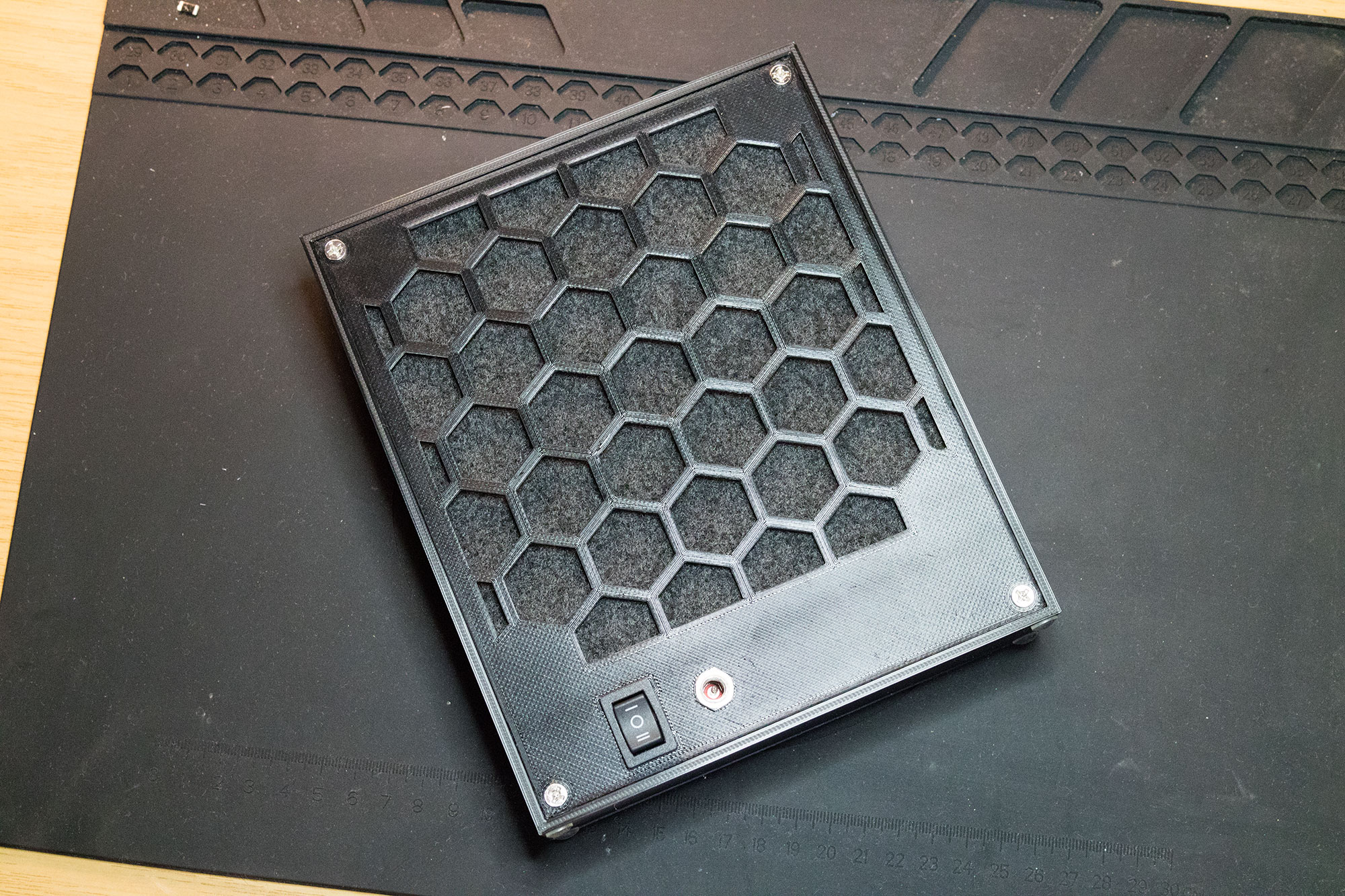
Now the filter can be cut and inserted. I have chosen a Xavax extractor activated carbon filter for this purpose. A single layer fits perfectly. The rear casing lid is also screwed on with four fan screws.
Conclusion
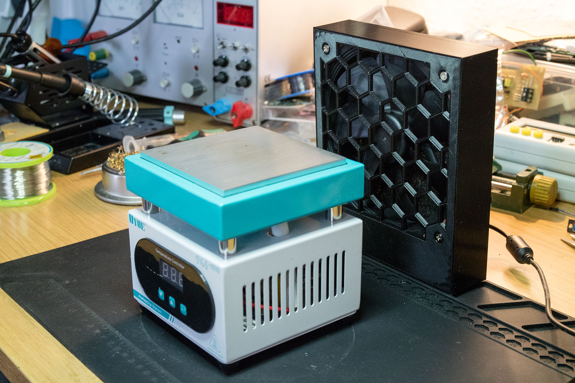
The solder fume extractor makes excellent throughput with the used fan, and easily extracts fumes at a distance of 30cm. Even at half power, the filter works amazingly well. This project should definitely not be missing in any workshop!