SP USB LCD
USB LCD prototype with EA-DOG for a firewall appliance
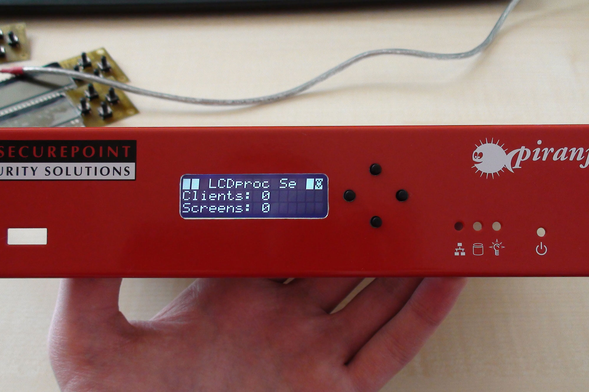
During my internship at a firewall manufacturer in Lüneburg, I was given the task of integrating a front panel display into the existing security appliance hardware. Inside the appliance there was a USB port on a pin header, so I had the idea of using it for my display.
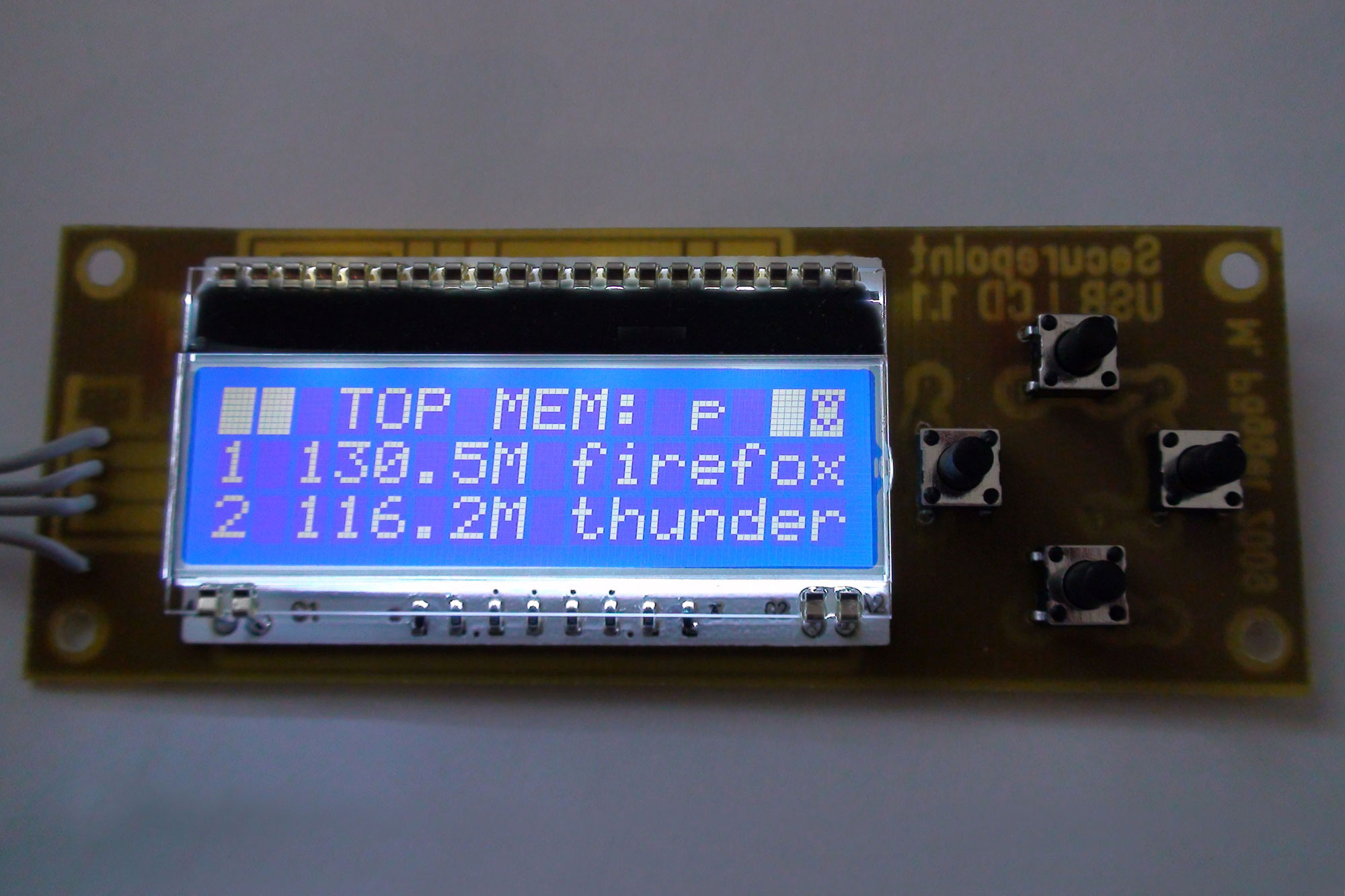
The firmware for the microcontroller is based on an adapted version of the LCD2USB from Till Harbaum. For space reasons between front panel and mainboard (about 1cm clearance) I chose the EA-DOG display series from Electronic Assembly. Electronic Assembly offers different backlights and chip on glass displays, the user can combine them as desired. The offer ranges from FSTN positive / negative to STN positive, negative, blue and reflective LCDs. These are available with 16 characters each and one two or three lines, there are also 6 matching backlight modules.
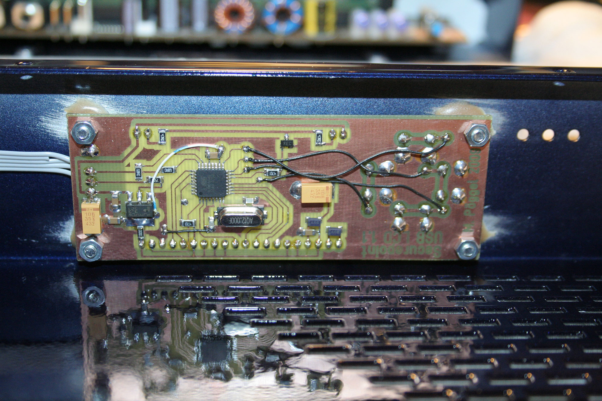
0.7mm PCB material was used, almost all components are assembled as SMD components on the backside. On the prototypes, a few connections are drawn as wires, which will be done with a double-sided layout in the later production.
The EA-DOG display uses a Sitronix ST7036 controller. This is "almost" compatible with the standard HD44780, but has some quirks in the initialization. On the one hand it is possible to run the display with 3.3 volts. The voltage needed for the display is then generated by the charge pump integrated in the controller. In addition, this can be modified by command, in order to control the contrast. This functionality was also rewritten accordingly in the driver. Like in the original, the backlight can be switched or dimmed.
In my circuit the Atmel and LCD are completely supplied by 3.3 volts to meet the USB specifications. Since the ATMega8 used by Till Harbaum can only be operated up to 4.5 volts, I replaced it with an ATMega48.
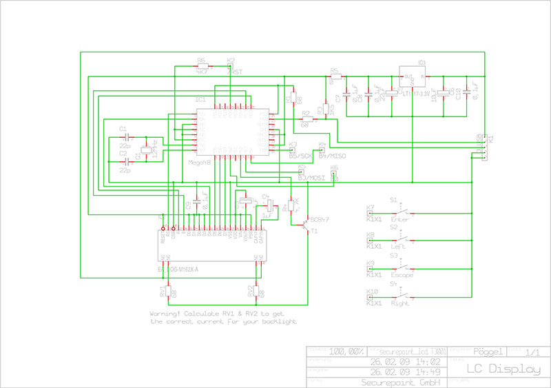
Unlike the original, I also added two more buttons. Because LCDproc does not interpret the data of the keys as bit patterns but as scan codes, I adapted the firmware to return these scan codes (1 = key1 [ESC], 2 = key2 [UP], 3 = key3 [ENTER], 4 = key4 [DOWN]) to keep the compatibility to existing hardware. However, pressing several keys at the same time can then no longer be processed. (But this is not supported by LCDproc anyway).
Configuration of LCDproc
The two-line LCD is fully compatible. To control the three line display some adjustments have to be made in LCDd.conf. Because the second line in the DDRAM starts immediately after the first, there is a linear addressing. So the extended mode must be activated.
Furthermore each next line starts 16 decimal or 0x10 hexadecimal positions upwards. Default in extended mode is 0x20. This setting can be adjusted with the parameter Line_Address, which was added in version 0.5-dev.
Default values for the contrast setting are 440 for a three-line LCD and 200 for a two-line LCD.
All other settings can be found in the LCDproc manual.
Important note for compiling the Atmel firmware: In the upper part of the ea-dog.h there is a macro to adjust the number of lines.
#define LINES 3
Conclusion
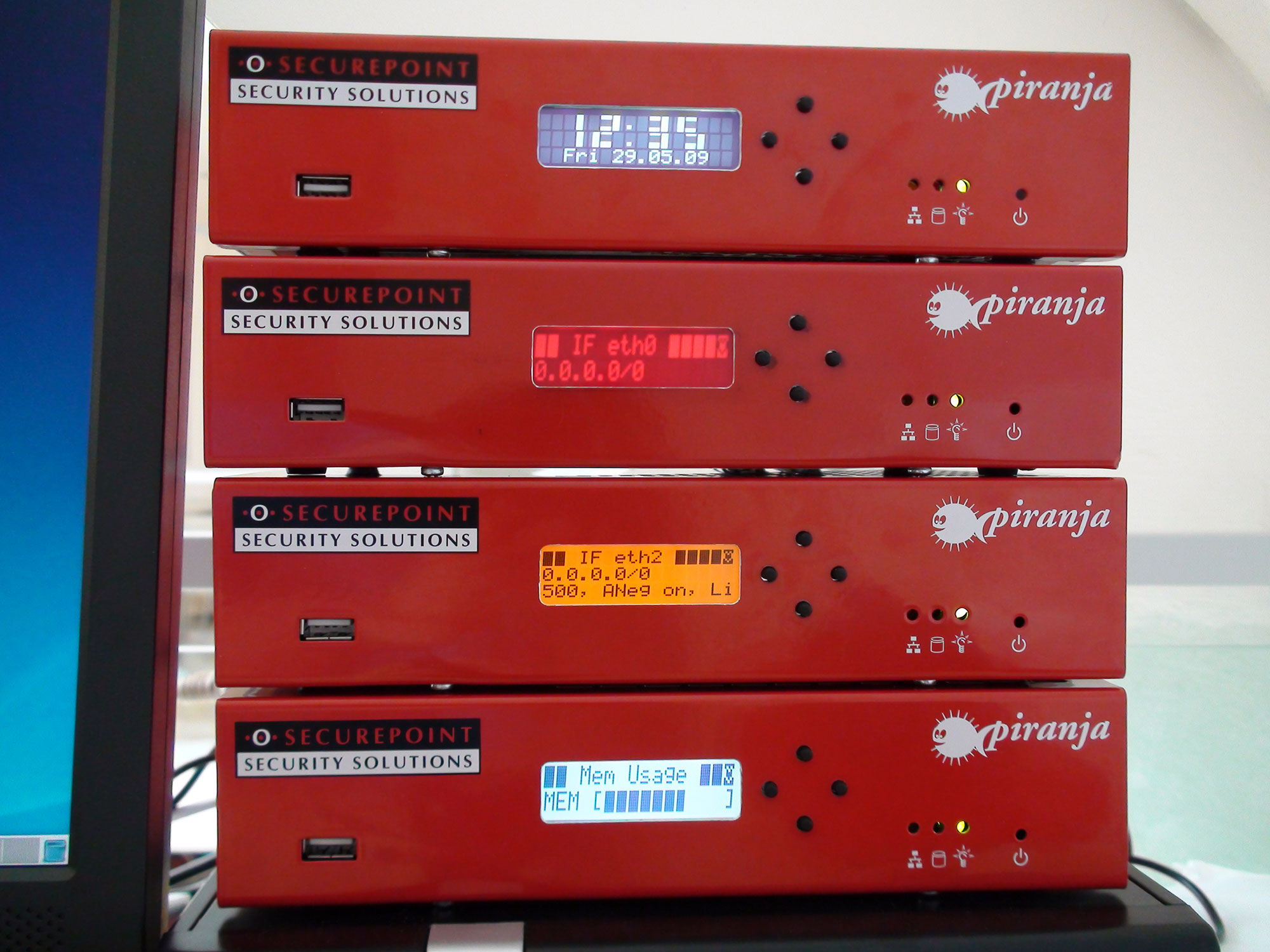
The completed prototypes were integrated into four Piranja firewalls. Especially the three-line displays resulted in a great interest among the staff.