Inverter
12V to 230V 50Hz sine wave inverter (100W)
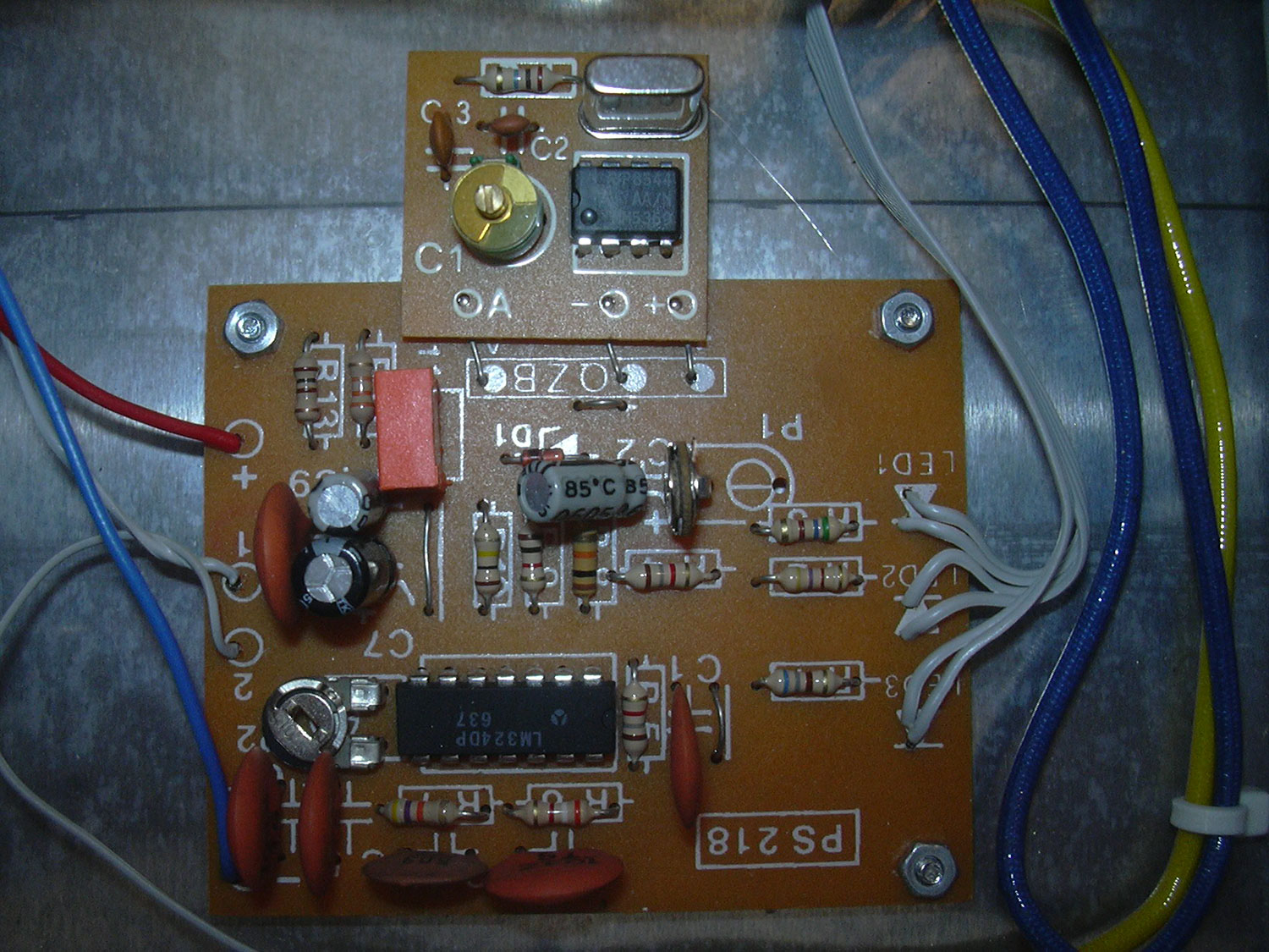
The main part of the circuit is an old inverter kit from the no longer existing company Professional Systems. The 50Hz clock signal is generated from a quartz, which drives a transformer with center tap alternately with two transistor output stages. An overvoltage protection protects the generated 230V against voltage peaks. On the 12V side, a self-built undervoltage cutoff is added to protect the connected battery from deep discharge.
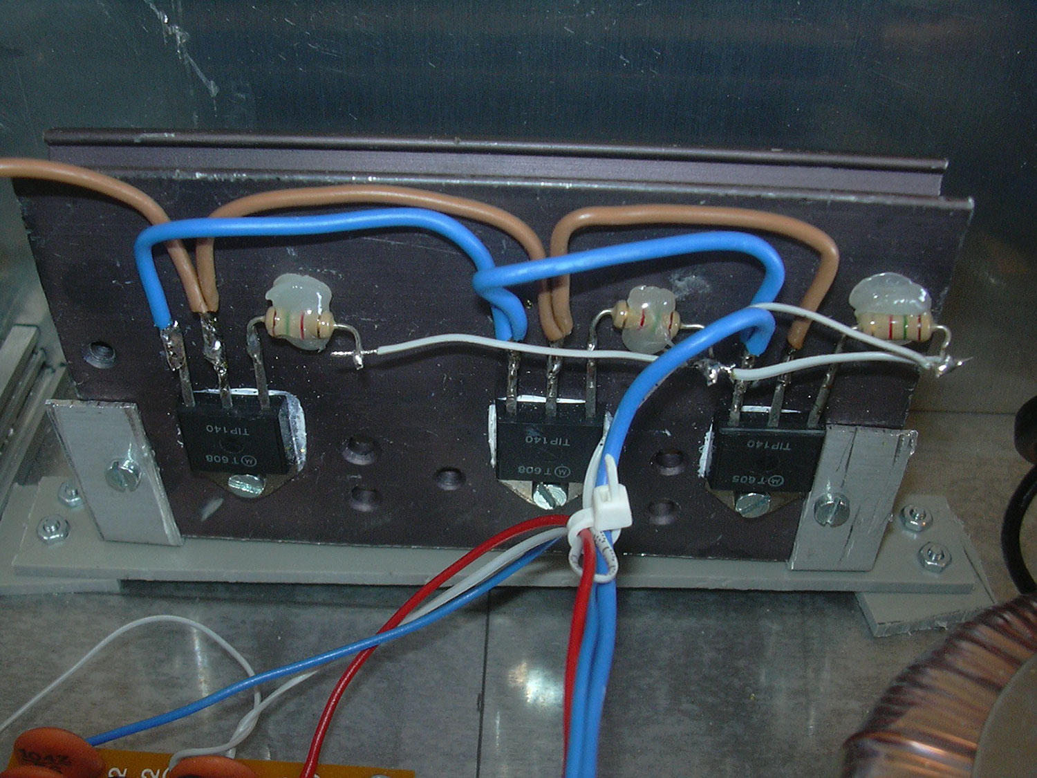
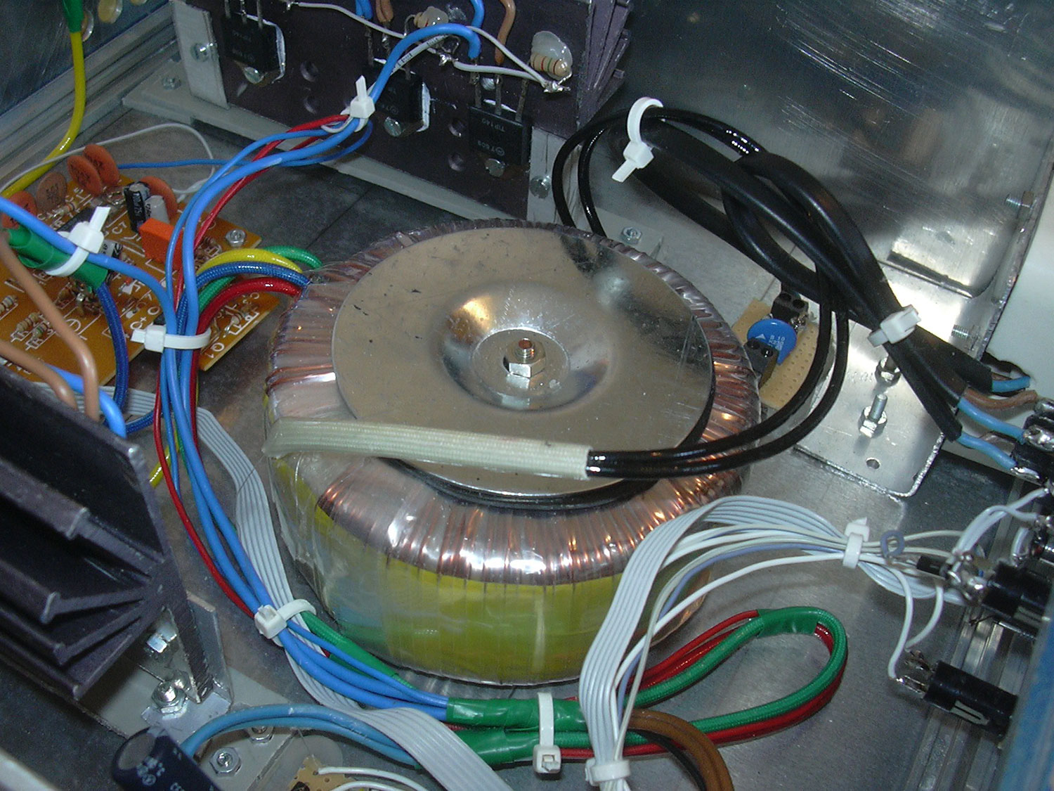
The main board contains a smaller board with the clock generator. The output stages consist of 3x TIP140 per side and drive the transformer windings alternately. The alternating magnetic field generates 230V on the line voltage side of the transformer.
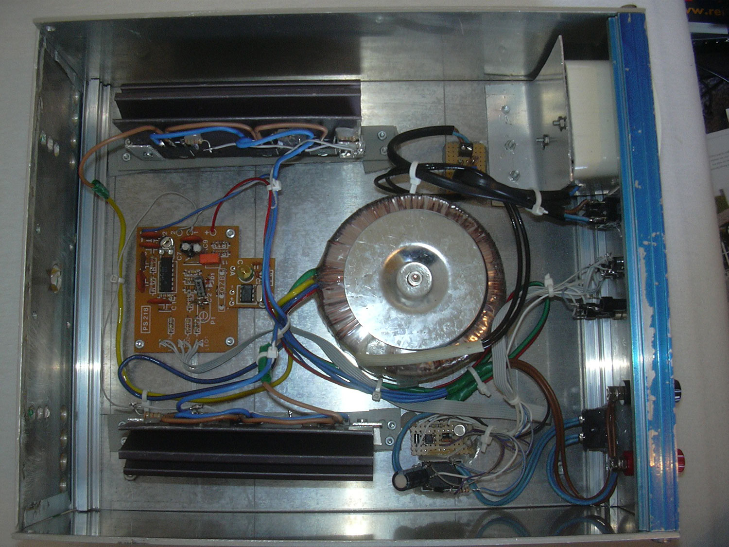
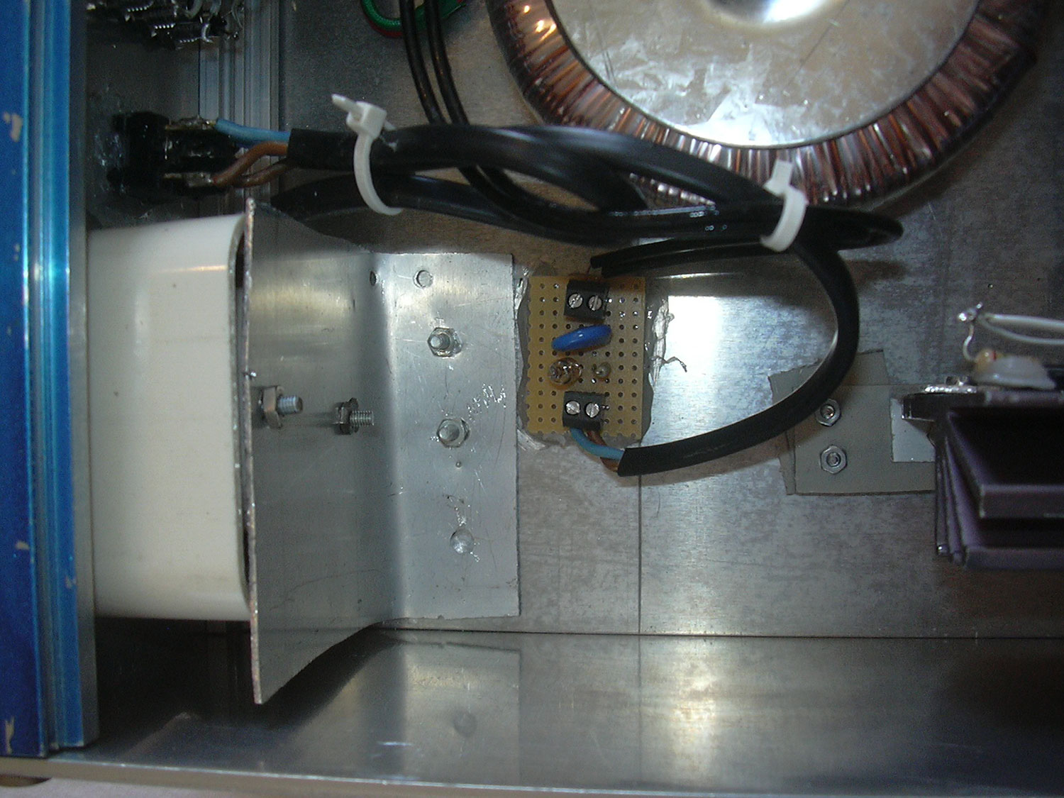
In the center there is a toroidal transformer. On the mains side there is a small board with a varistor as overvoltage protection and a neon bulb as voltage indicator. From there the power is connected directly to the socket.
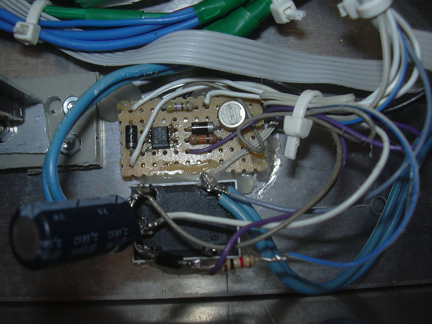
The undervoltage cutoff (left picture) is built with a comparator. For simplicity, a diode is used as reference voltage source. The second picture shows the backside of the front panel.
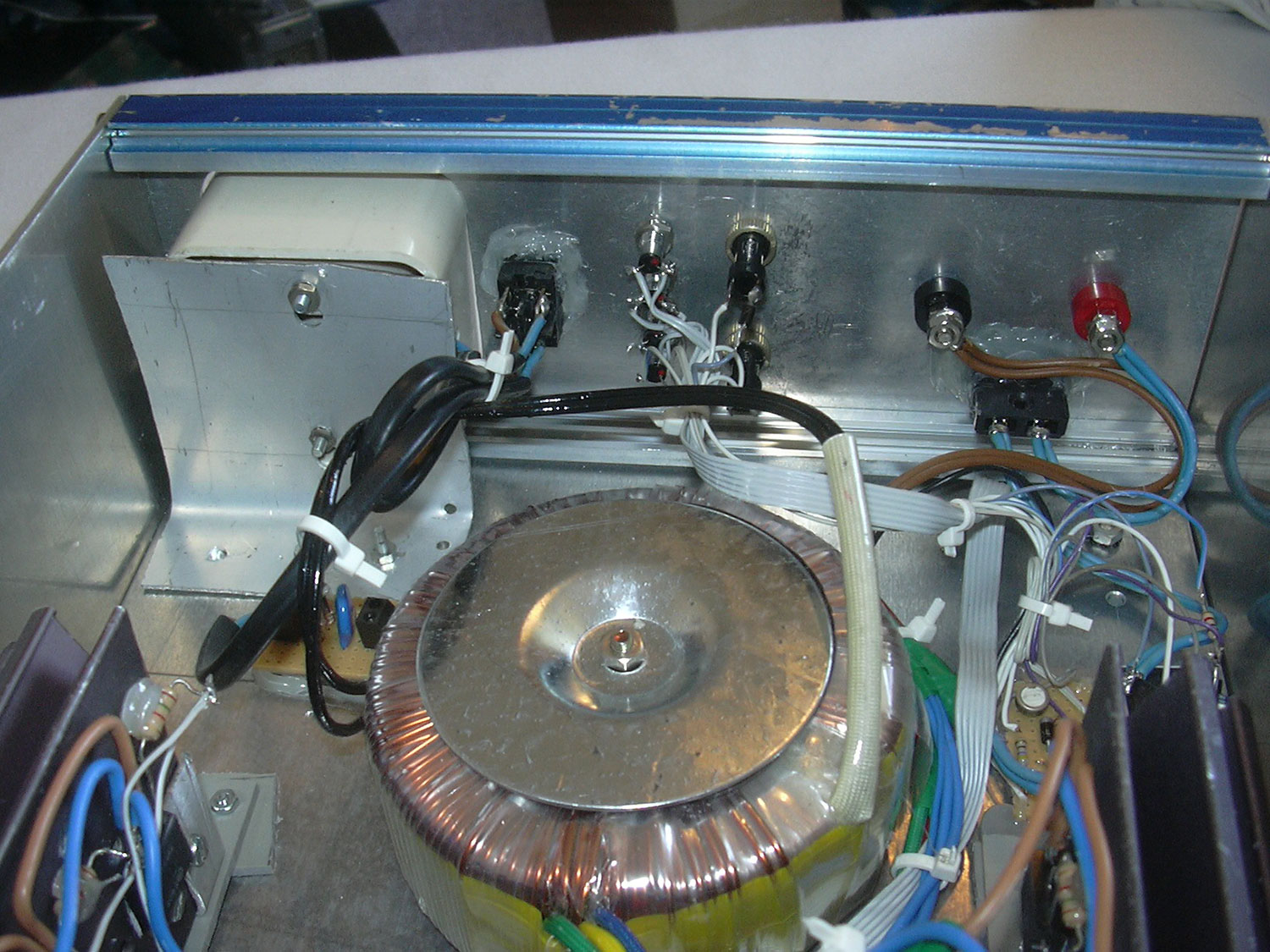
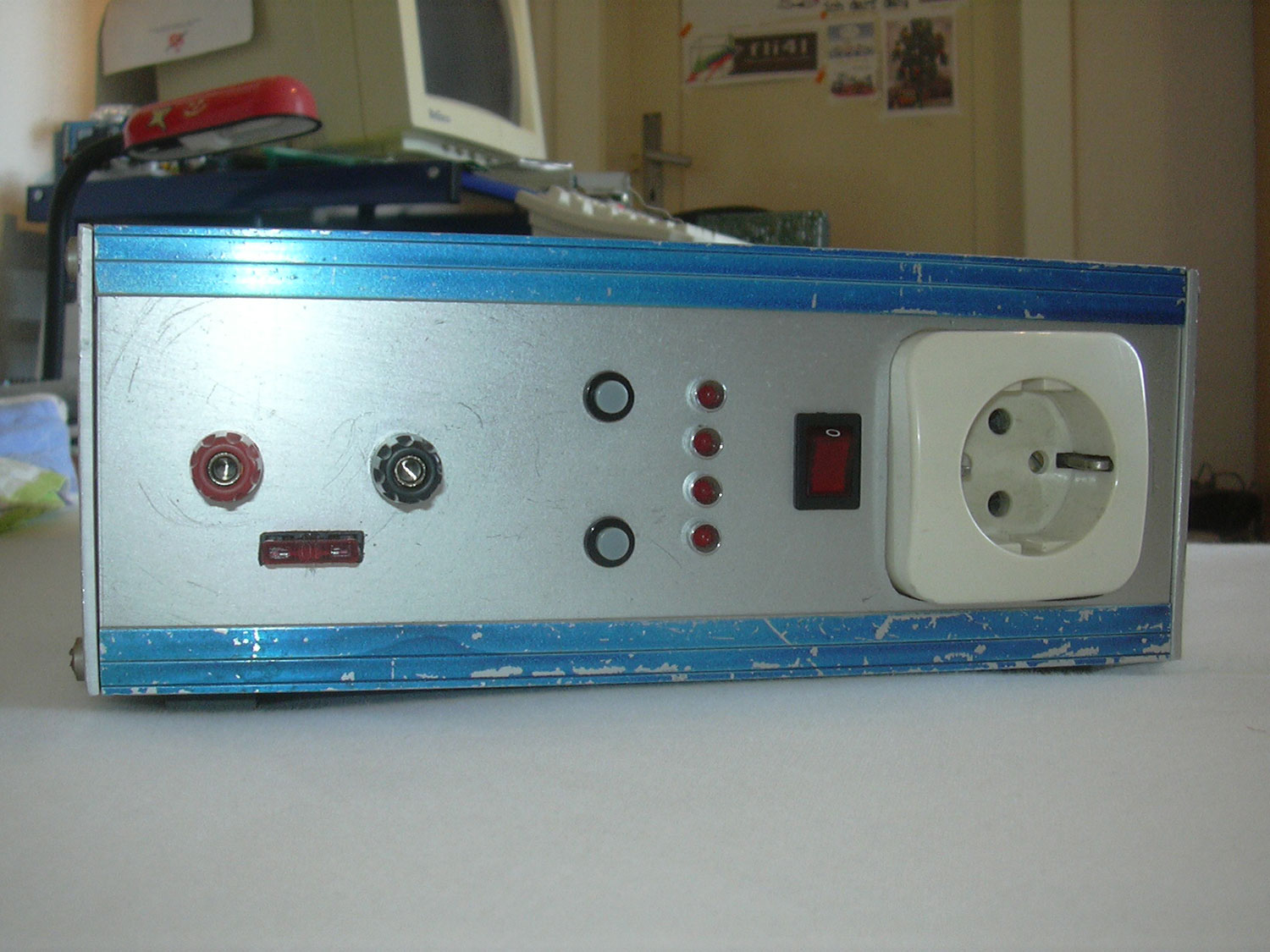
In the front panel there are 4mm sockets to connect the battery, a car fuse, on/off buttons, battery voltage indicator and the switch for the mains voltage and the socket. During outdoor operation the inverter (on the picture next to the battery under the table) was sufficient for exactly two movies with a 55Ah car battery.