
Nixie Power Supply (MAX1771)
High-Voltage Module for Nixie Display Tubes with MAX1771 Step-Up Converter
I didn't have the right power supply to build a clock using old Nixie tubes. The design of these tubes from the 1960s and 1970s is similar to that of a glow lamp, except that the digits or symbols they display are connected as separate cathodes. They require a high voltage of about 180V. Since there are various interesting circuits available online, I decided to go with a modular design.
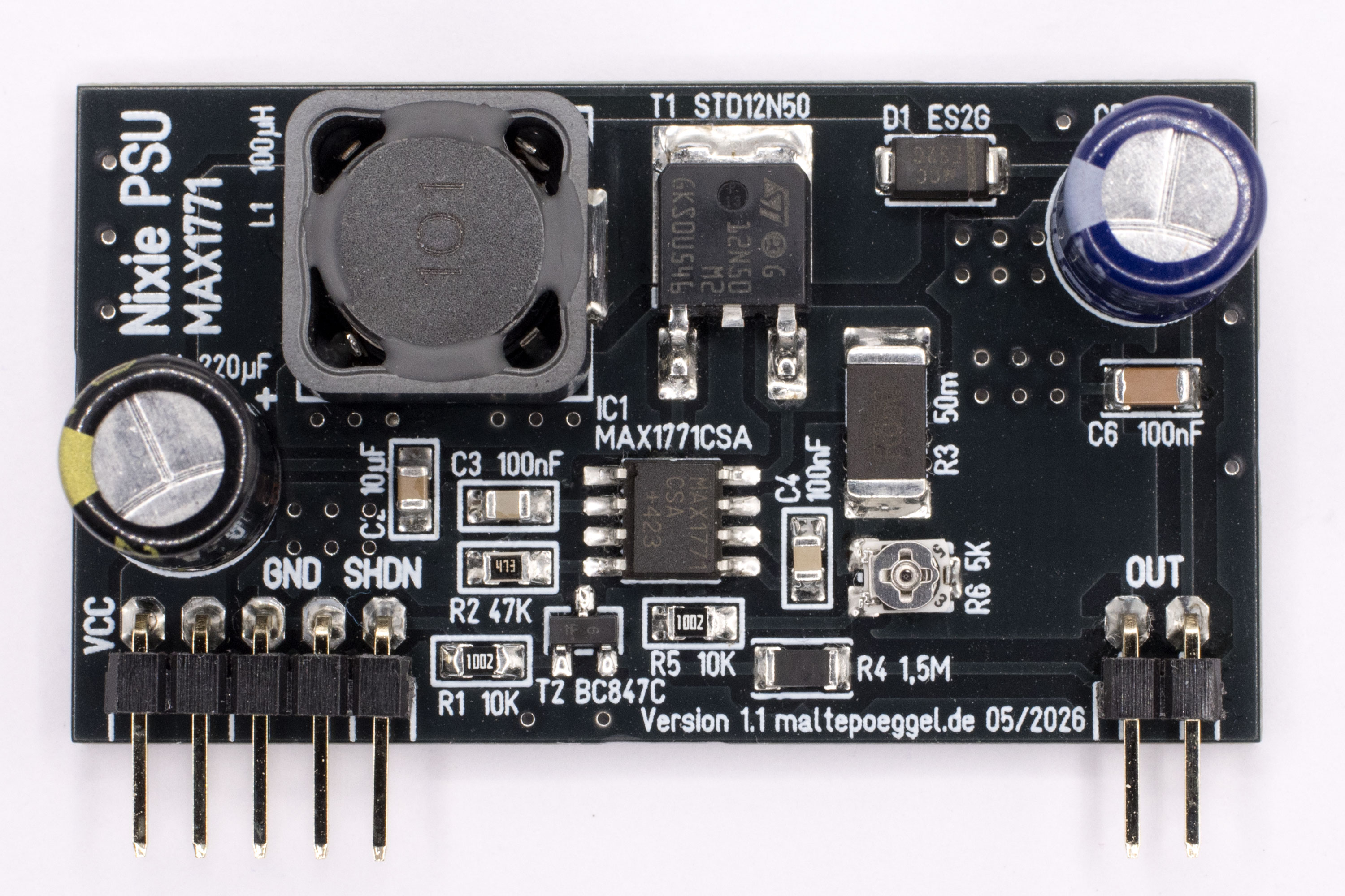
This module board uses the MAX1771 switching regulator IC and has the same pinout and dimensions as the first version with the MC34063. It generates an adjustable output voltage between 150 and 220V from a 12V input voltage. The circuit design is based on the website of Nick de Smith, linked below. Almost all components are surface-mount (SMD). The switching regulator operates at a high switching frequency of up to 300 kHz, making it extremely efficient.
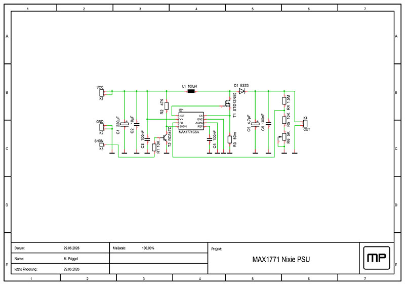
Circuit description
Capacitors C1-C3 filter the operating voltage. The switching regulator IC1 forms the heart of the circuit. R1, R2, and T2 activate the regulator when a voltage is applied to K3. The field-effect transistor T1, together with the inductor L1 and D1, forms a step-up switching regulator. Resistor R3 is required for the built-in current limiting. The output voltage is filtered by capacitors C5 and C6. Resistors R4, R5, and the potentiometer R6 form a voltage divider that provides feedback to the switching regulator. The potentiometer can be used to vary the output voltage.
Performance and Efficiency
In my measurements, an efficiency of 85% was achieved under various load conditions. Even under a 5-watt load, the voltage did not drop, making the module suitable for circuits with many or larger tubes. The Z5700M tubes I used, for example, are rated at 2.5mA per tube, which at 180V with an anode resistor results in 0.45W. This circuit is slightly more expensive, but is more efficient overall due to its high frequency, and also offers the ability to turn the high voltage on and off.
Project status
The project is not finished yet, component values may still change.
Links
- Nick de Smith - MAX1771 Nixie HV Switching PSU
- electronics-lab.com - HV Nixie DC-DC Switching Power Supply
Downloads
License
The PCB layout I created may be used freely for private use, but the author's name must remain on it (CC BY-NC-SA). The schematic is not subject to any restrictions..