
Nixie Power Supply (MC34063)
High-Voltage Module for Nixie Display Tubes with MC34063 Step-Up Converter
I didn't have the right power supply to build a clock using old Nixie tubes. The design of these tubes from the 1960s and 1970s is similar to that of a glow lamp, except that the digits or symbols they display are connected as separate cathodes. They require a high voltage of about 180V. Since there are various interesting circuits available online, I decided to go with a modular design.
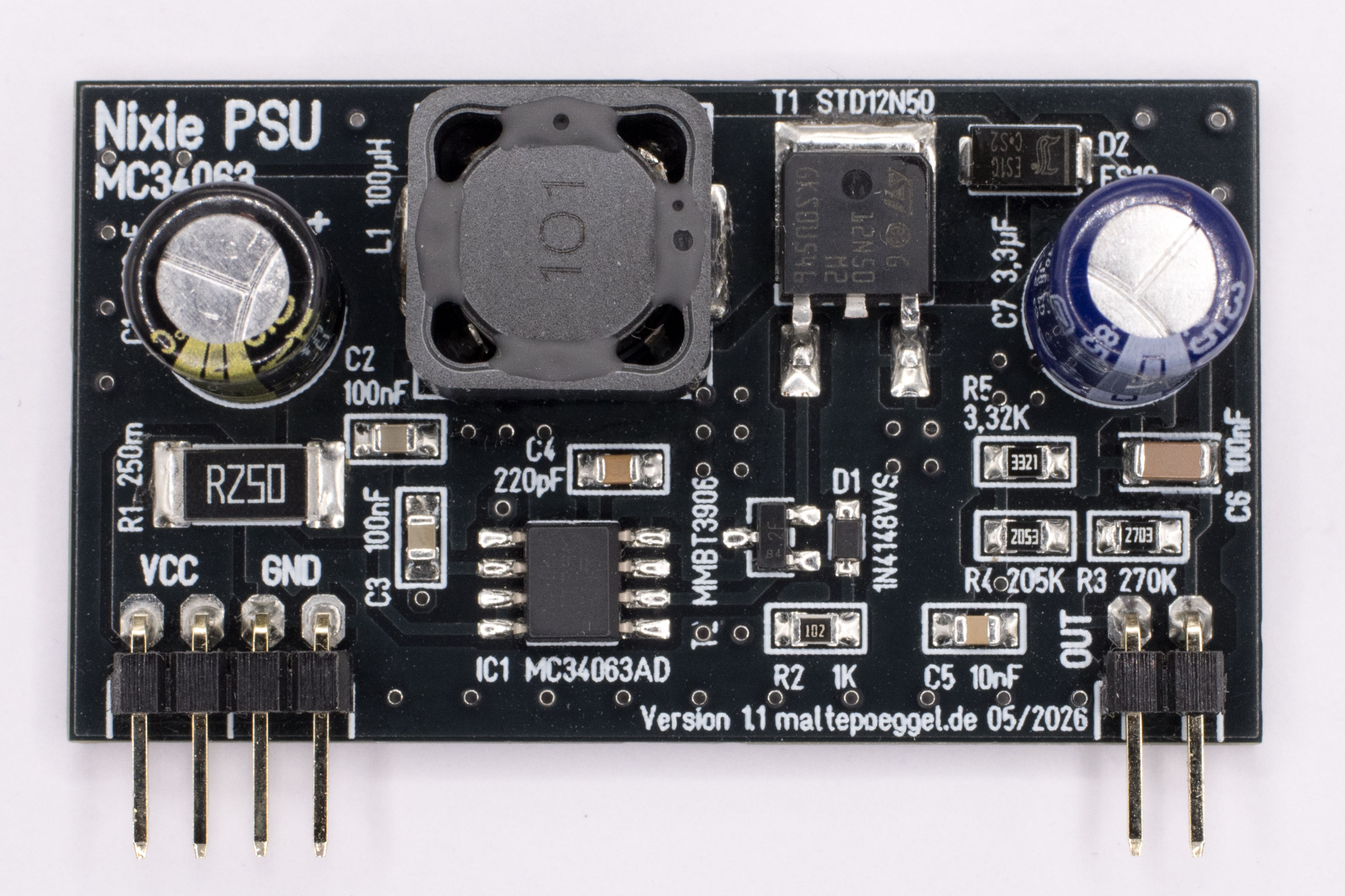
The module board shown above uses the inexpensive and widely available MC34063 switching regulator. (For an alternative, see MAX1771) It generates a fixed output voltage of 180V from an input voltage of 12V. The circuit design is based on Threeneuron's blog linked below. Almost all components are surface-mount (SMD). The MC34063 uses PFM (pulse frequency modulation). As a result, the switching frequency varies depending on the load. By adjusting the capacitor on the TCAP pin, I was able to increase the switching frequency and efficiency of the converter. Additionally, the IC does not have a push-pull output stage, so this is added via external circuitry using a transistor to switch the MOSFET’s gate as sharp as possible.
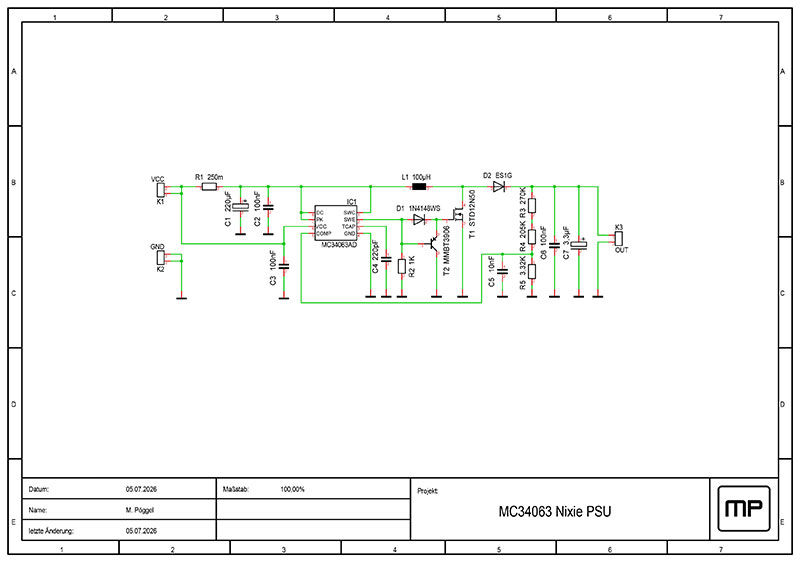
Circuit description
Resistor R1 is required for the built-in current limiting. Capacitors C1-C3 filter the operating voltage. The switching regulator IC1 forms the heart of the circuit. Its maximum switching frequency is determined by the timing capacitor C4. The combination of D1, R2, and T2, together with the internal transistor in the switching regulator, forms a push-pull output stage. This controls the field-effect transistor T1, which, together with the inductor L1 and D2, forms a step-up switching regulator. Resistors R3, R4, and R5 form a voltage divider to provide feedback to the switching regulator. The upper section is split across two resistors to increase the voltage rating. SMD resistors in 0805 packages are often rated for only 150V. Capacitor C5 filters the feedback voltage. The output voltage is filtered by capacitors C6 and C7.
Performance and Efficiency
In my measurements, an efficiency of 70% was achieved under various load conditions. The switching frequency varies between 1.5 and 75kHz, which sometimes falls within the audible range. Nevertheless, I could not hear any noise from the coil. Even under a 5-watt load, the voltage did not drop, making the module suitable for circuits with many or larger tubes. The Z5700M tubes I used, for example, are rated at 2.5mA per tube, which at 180V with an anode resistor results in 0.45W. This circuit is very cost-effective.
Links
Downloads
License
The PCB layout I created may be used freely for private use, but the author's name must remain on it (CC BY-NC-SA). The schematic is not subject to any restrictions..