AVR Flashlight Controller
700mA constant current driver for flashlights with one lithium cell
I am one of those people who sometimes order flashlights from China.
For little money you get a lot of technology: A solid aluminum housing with rubber seals, a high-power LED, suitable driver electronics - mostly powered by one or more 18650 lithium batteries.
Since I actually always have one of those lamps in my pocket, the word got around in my friends' circle as well. There was a real flashlight competition, and thus also lamps with less good driver electronics fell into my hands. High time to start tinkering!
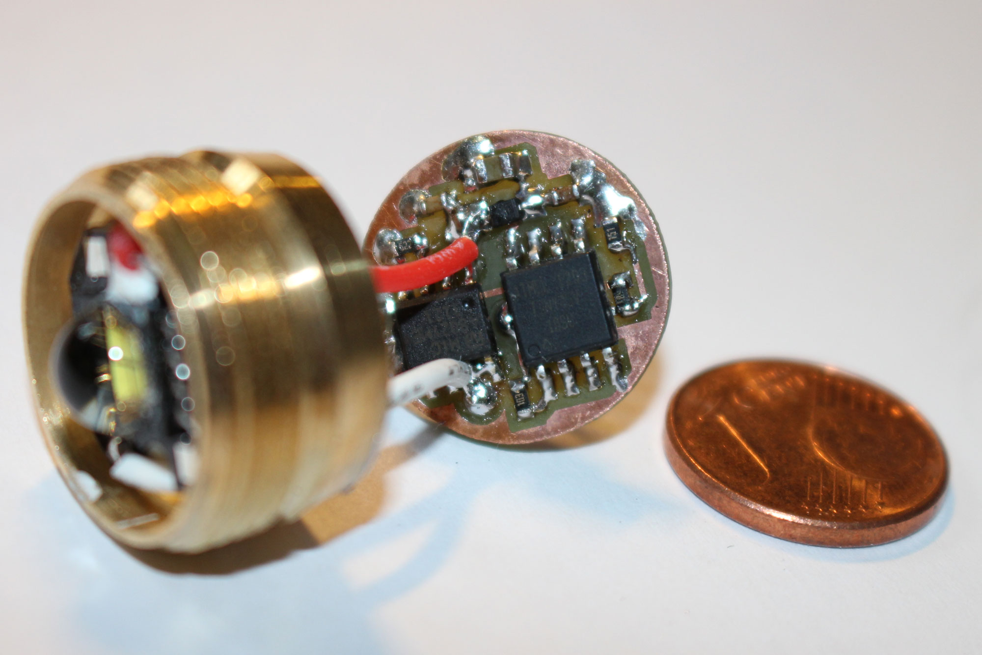
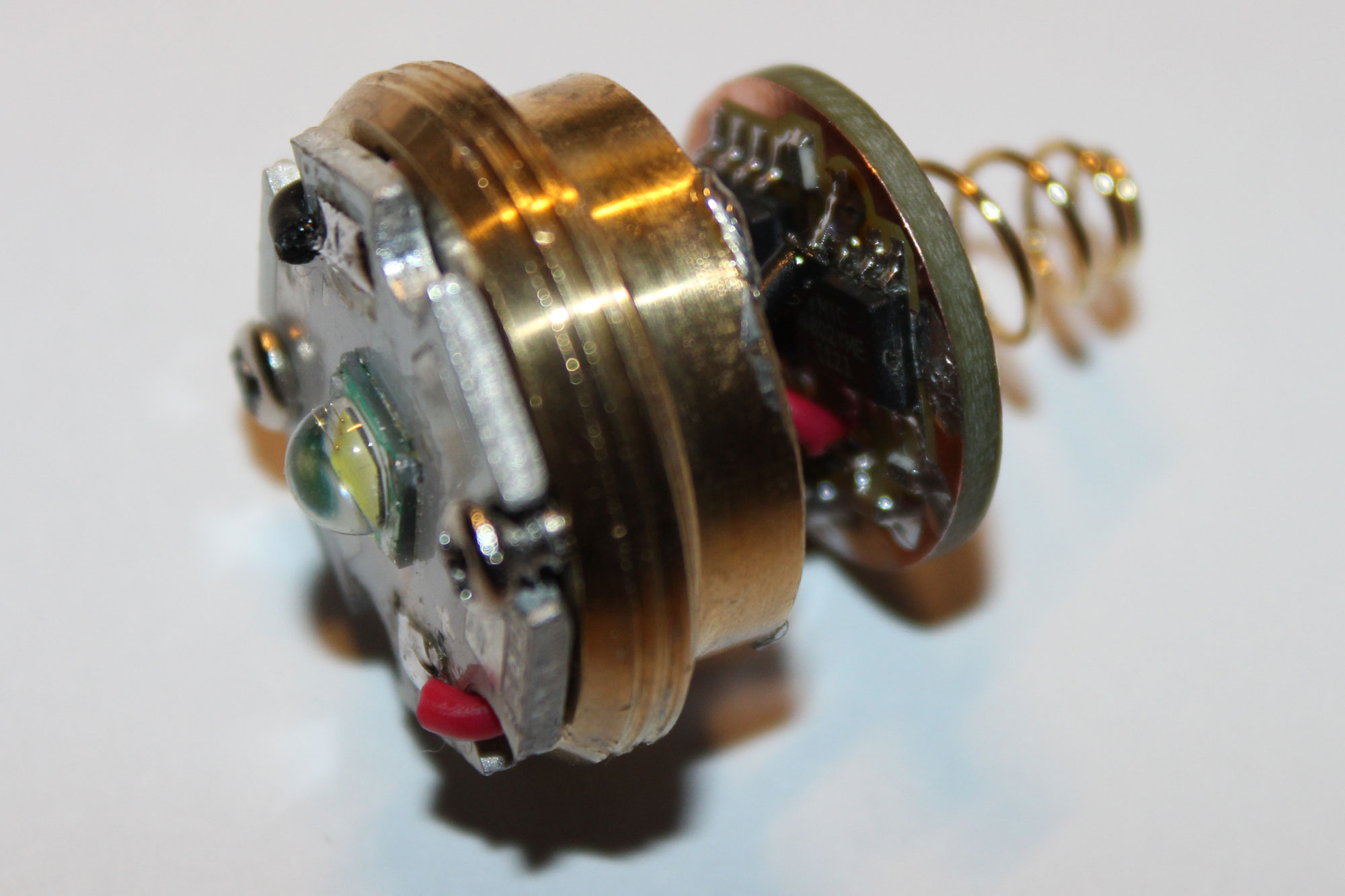
Such a driver is often capable of more than just limiting the LED current. A microcontroller makes it possible to switch between different brightness levels or blinking patterns. The driver is attached in form of a small circuit board behind the LED. Both are attached to a brass block, which also ensures the heat dissipation of the light emitting diode, and screwed with a thread in the head of the lamp. On the back side, the contact spring is attached to the positive pole, the negative pole is soldered to the brass insert.
Some time ago I got an Ultrafire TH-T60 with a defective driver as a gift. A circuit board breakage caused the LED to light up only when the head was not screwed completely tight. With a multilayer board layout containing components close together, this is nothing that can be found and repaired with a little effort. On further analysis, I also found that this lamp was not even regulated to constant current. Microcontroller, Mosfet - current is limited at most by the internal resistance of the battery. This confirms the statement that the brightness was initially very high, but quickly decreases. Thus, even the 975(!) lumens claimed by the manufacturer are only reached over a short period of time.
To protect the LED and to offer a more constant brightness, I have chosen the constant current LED driver MIC4802 for my own controller. This is a linear regulator with programmable current limiting and PWM input. Switching regulators are not suitable for operation with only one lithium cell, the forward voltage of the LED is only slightly below the battery voltage.
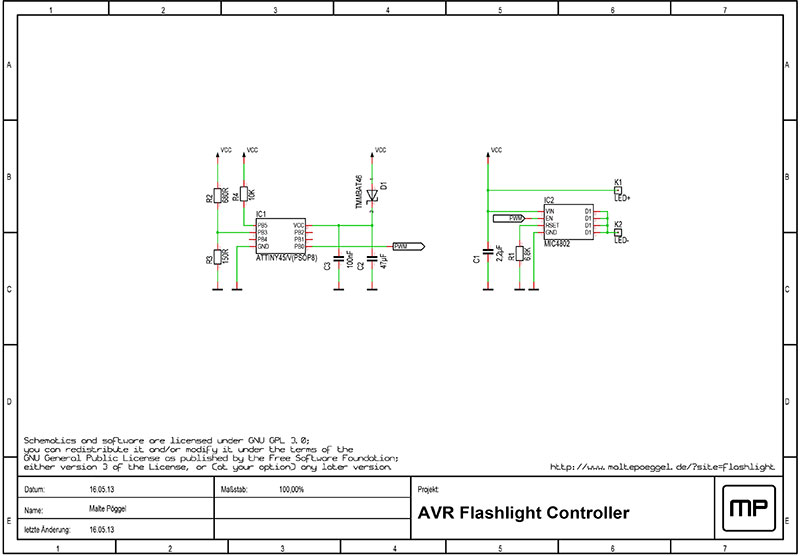
As mentioned before, some flashlights offer dimming and flashing functions. For this purpose an ATTiny45 is used, which is connected to the PWM input of the MIC4802. The microcontroller has to detect the toggle request by short interruptions in the power supply. For this I came up with the following trick: The controller gets its operating voltage via a shottky diode and a capacitor. The reset pin is connected directly to the power supply via a resistor. If the voltage drops for a short time, the controller gets a reset pulse. A flag in the MCU control register offers the possibility to determine whether it is an external reset or the power on reset.
There is always some critic about the brightness levels and flashing functions. One person finds three levels too few, the other does not need the stroboscope. To solve these problems, I have stored various "mode sets" in the firmware:
- Brightness in 3 steps
- Brightness in 5 steps
- Brightness in 7 steps
- Brightness in 5 steps, stroboscope, SOS
- Brightness in 5 steps, flashing, stroboscope, short flash
- Brightness in 5 steps, flashing, stroboscope, short flash, SOS, alipine distress, up and down thread, spooky flicker (pseudo-random number generator)
To change the mode set, the mode must be switched 20 times in a row (tap briefly, keep pause time short) and then wait longer than 2 seconds. The lamp flashes x times according to the set and then remains dark. After a complete power off the mode set is active.
The flashlight can either always start with the brightest level, or continue the last mode. This can be switched by tapping 25 times and then waiting (as above) and is acknowledged 7 (save state) or 8 (start with full brightness) times flashing.
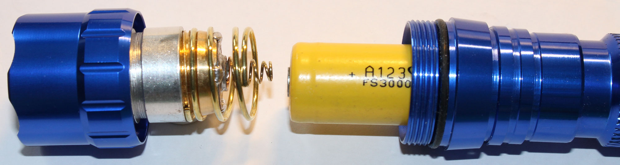
A voltage monitor ensures that the flashlight switches off when the supply voltage drops below the discharge voltage. The shutdown voltage can be adjusted in the main.h to the respective battery type (eg LiIon or LiFePO4).
The double sided PCB was etched by hand as usual. Afterwards it was cut out with a fretsaw and fitted with a key file. Above on the left the desoldered original board is shown, on the right you can see both layers of the new board.
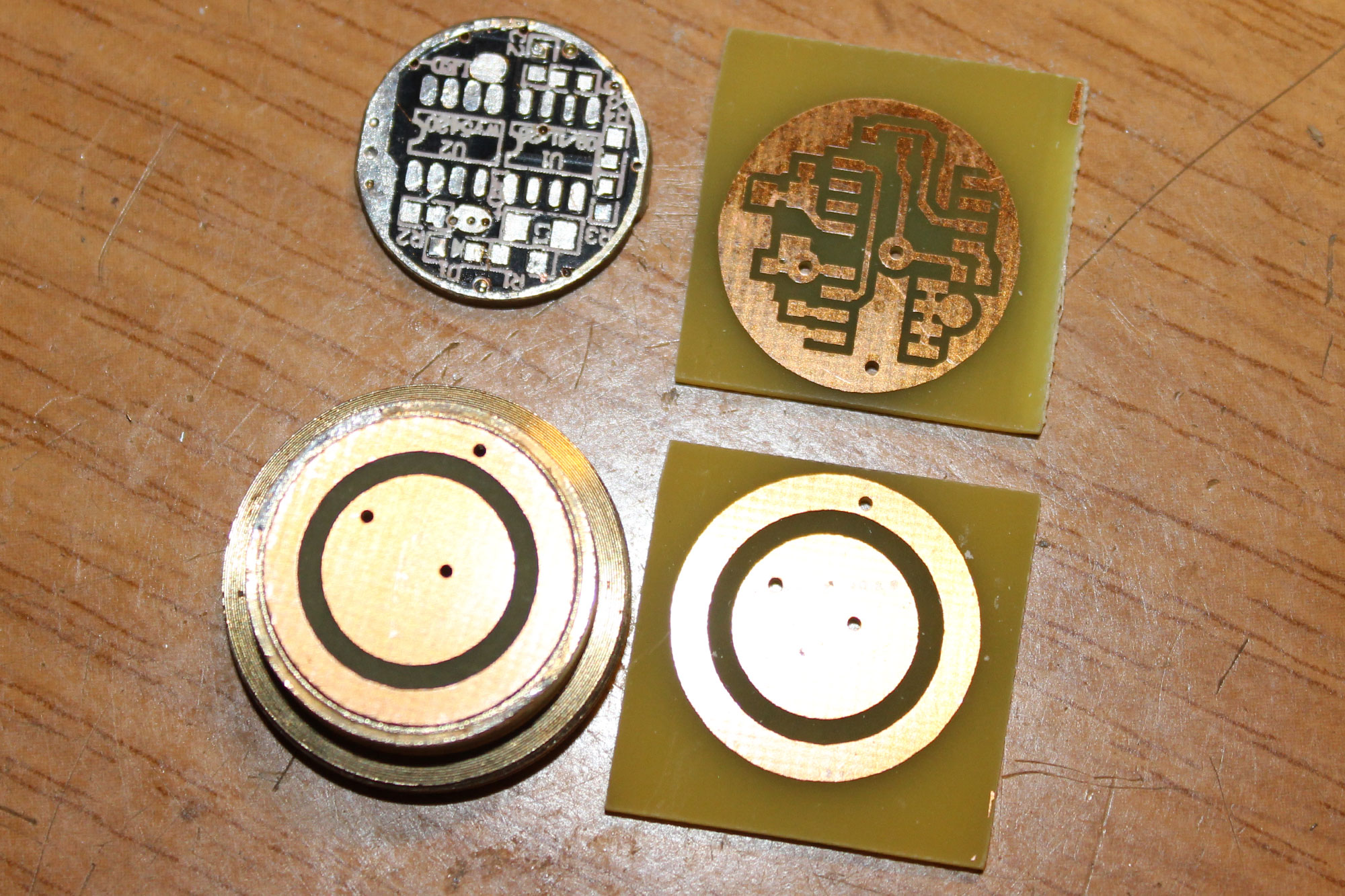
Plated through vias can be easily created using wire soldered on both sides. The resistors and some capacitors have 0603 SMD packages.
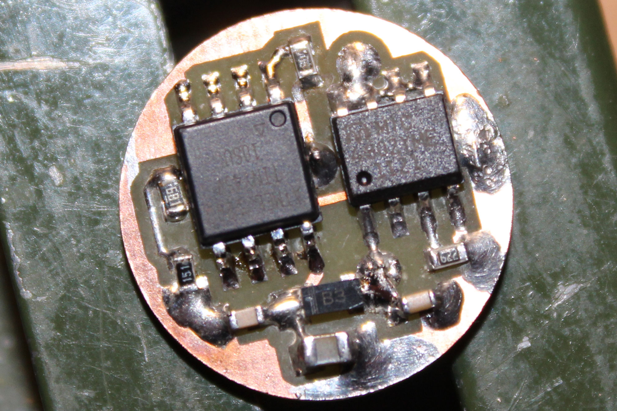
The MIC4802 has a so-called "Exposed Pad", a pad on the bottom side which is supposed to dissipate the heat. Some solder is applied to the board, then the chip is placed on the preheated board and soldered by hot air. The chip should be soldered a little bit offset, otherwise the pad will short-circuit with the trace to the PWM pin, which is routed underneath the chip. The remaining 8 pins can be soldered by hand.
Last but not least there's just some mechanical work to do. Solder the contact spring, solder the ground of the PCB with the brass insert, assemble the reflector and LED, done!
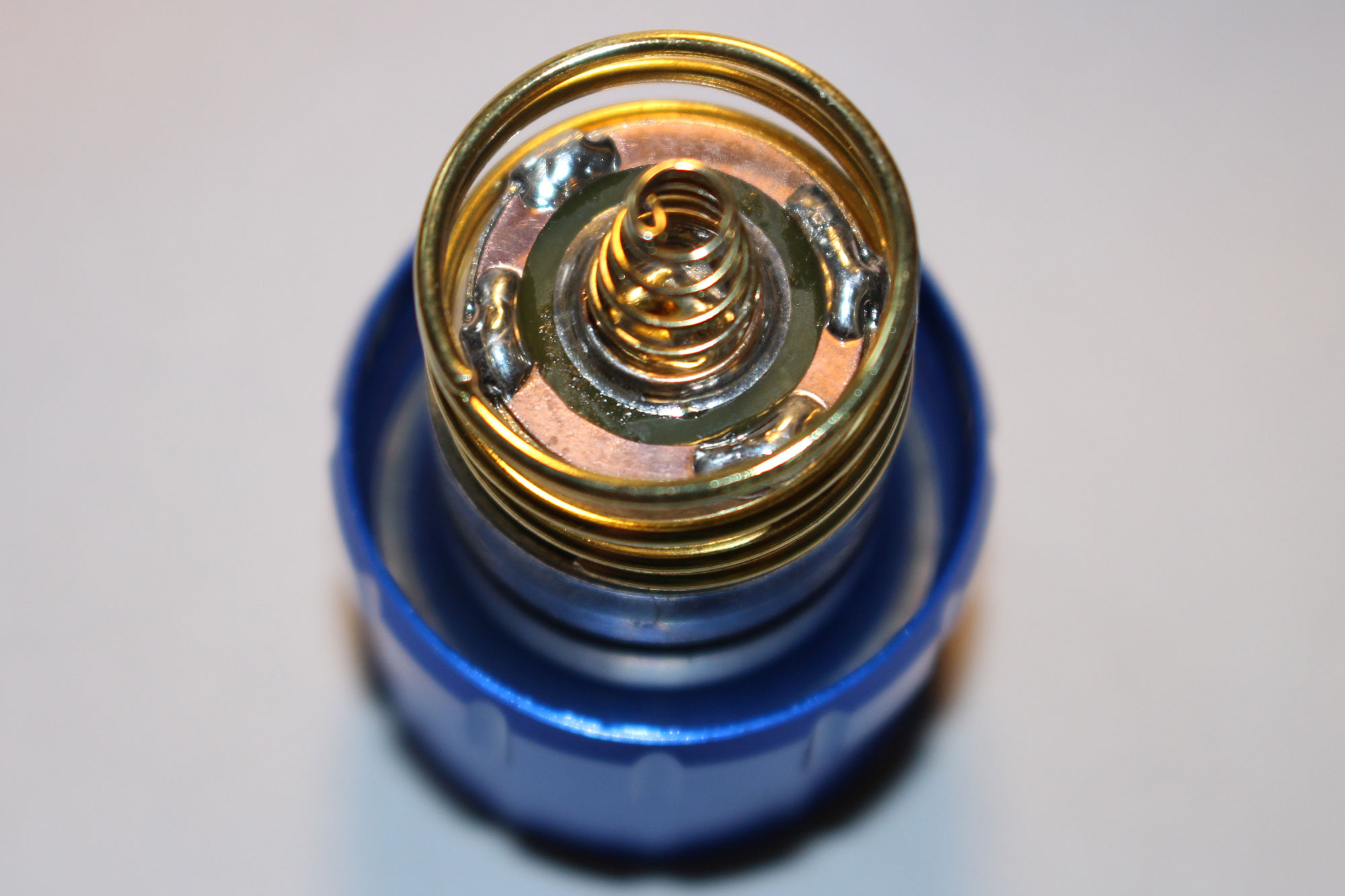
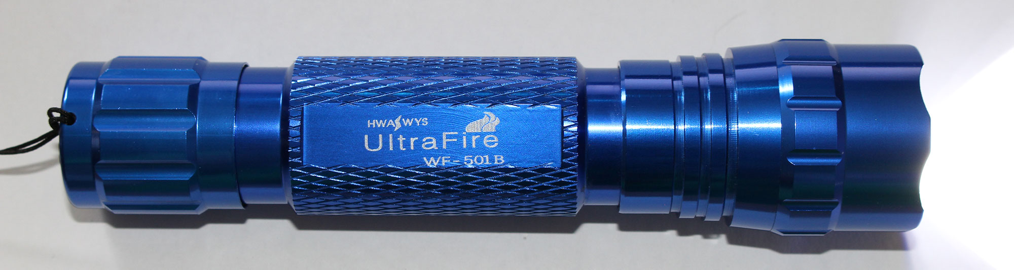
By the way, the picture shows a WF-501B with a blue anodized case. This one already has a usable driver out of the box, but it doesn't have as many functions.
Video - First tests
Have fun tinkering with it!
Downloads for the project
Related links
- Flashlight Wiki - AVR Drivers
- BudgetLightForum - How To Build a Flashlight With Perfect Modes (BLF VLD)