Lithium Power Pack
DIY mobile battery pack
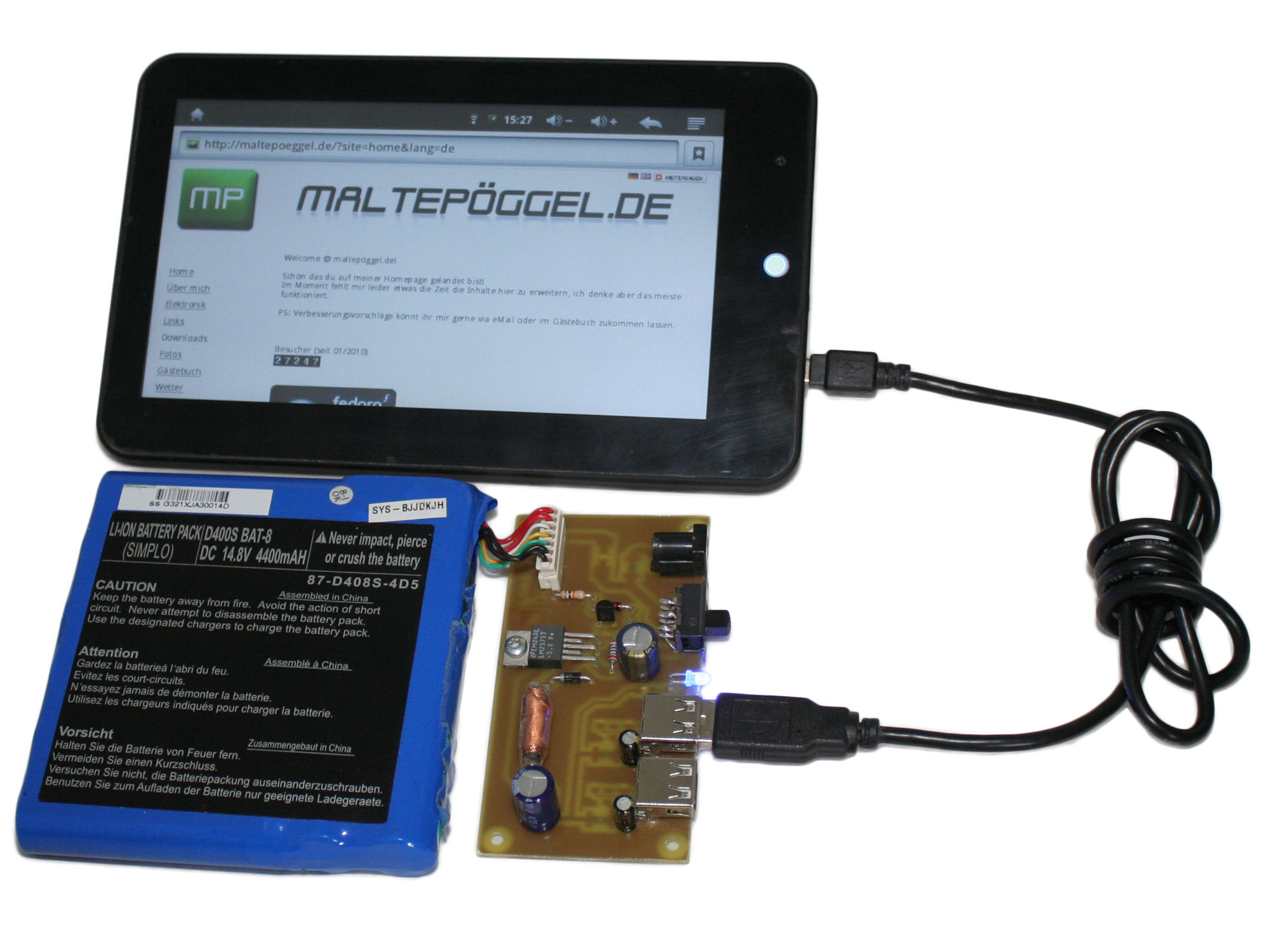
Who hasn't experienced it - you're out on the road and the battery always dies at the most unfortunate moment. Whether it's a cell phone, PDA, tablet PC or MP3 player; today's devices are real power guzzlers. However, luckily almost every device can be recharged via USB. Therefore, the goal of this project was to design a USB power supply for traveling.
Now the question is why build it yourself, similar devices are already available on the market. I did a little comparison and came to the conclusion that the mobile battery packs in the cheap price segment are usually only enough for one or two battery charges. This is rather unsuitable for longer trips - and I generally tend to forget recharging.
During a look into my tinkering box, a battery pack fell into my hands, which I had removed some time ago from a defective notebook (thanks to Beat S.). This battery pack was not mounted as a plug-in unit (as it is usually the case) but behind a cover and connected to the mainboard with cables.
After some charging and discharging with my Akkumatik, the condition was found to be good - almost the full capacity is still preserved after 5 years (manufacturing date is written on the back of the battery).
The next step is to find a solution to charge the battery safely. All lithium batteries are charged using the CC-CV (Constant Current - Constant Voltage) method. In this process, the battery is first charged with a constant current up to a maximum voltage, and then later with a constant voltage. If the charge current falls below a minimum level, the charging process is terminated.

A big problem is to meet the final voltage limit. This must be accurate to 50mV, otherwise metallic lithium is deposited and the battery becomes thermally unstable. There is a risk of explosion and fire, so be careful when handling LiIon and LiPo batteries.
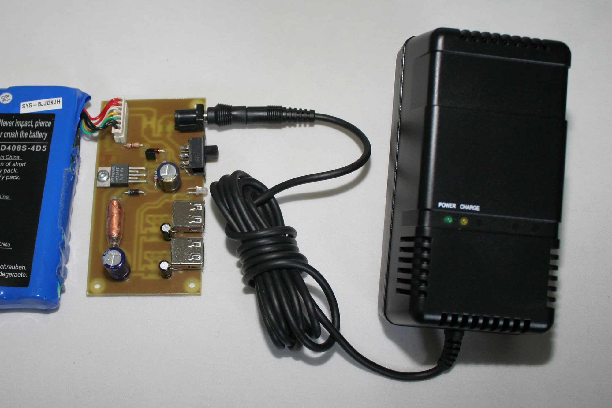
For safety reasons, I therefore decided to use an external charger. Ansmann offers a ready charger (LIC 3-4) in the form of a plug-in power supply.
This can be set to appropriate voltages for 3 to 4 cells with individual voltages of 3.6 or 3.7 volts and is available in stores for about 30 Euros. A suitable adapter set to various plugs is also included in the kit!
The charger must never be connected to the battery with reverse polarity, as this will destroy the charging electronics.
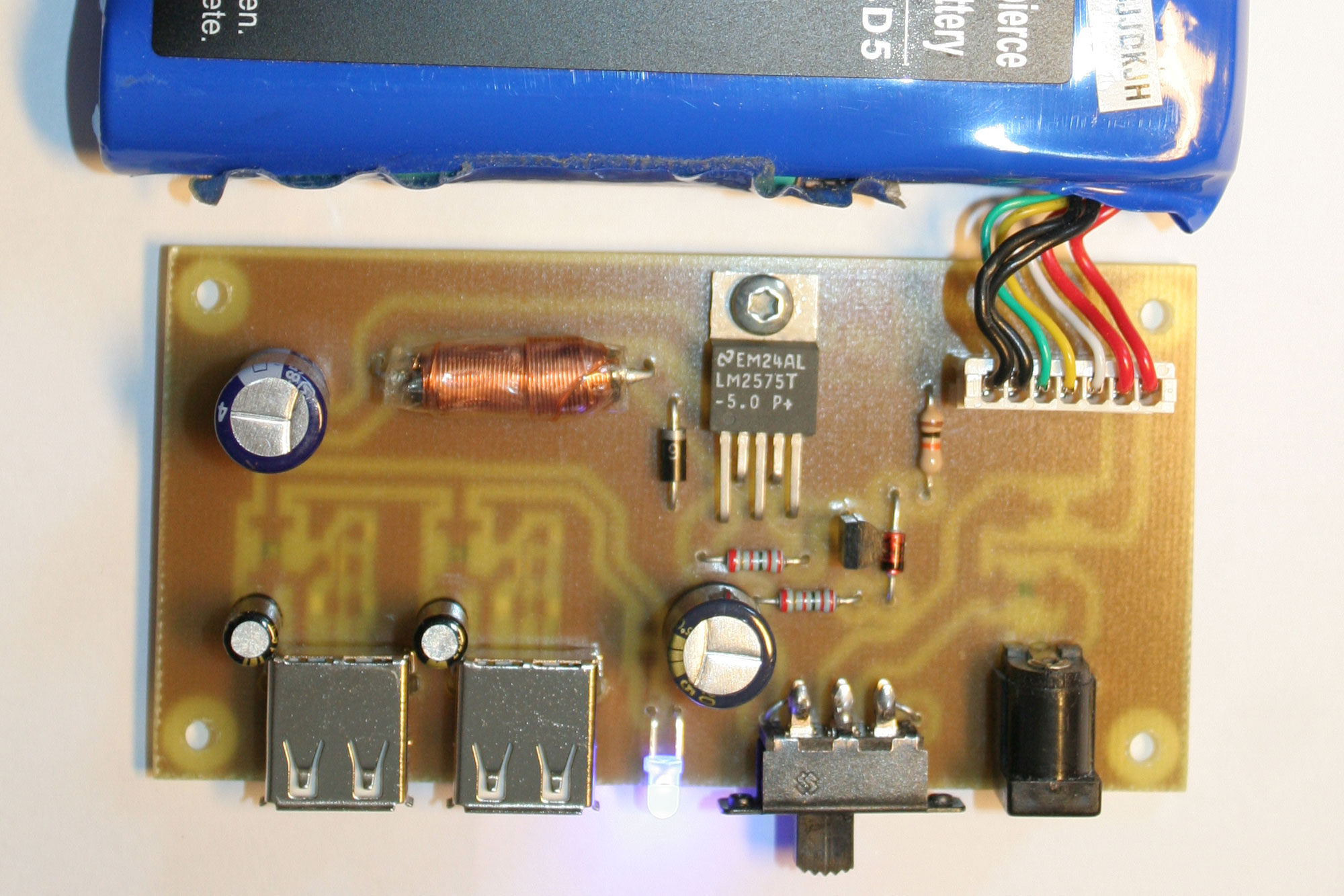
For the generation of the 5V voltage on the USB ports a LM2575T-5.0 is used. The switching regulator delivers up to 1 Ampere, to protect the battery a deep discharge protection consisting of R1, R2, R3, T1 and D2 is built. With the 10V Zener diode, the switching regulator is switched off when the battery voltage falls below approx. 11.5 volts. In this mode the circuit only consumes about 200μA.
The USB ports are each protected by a 500mA polyfuse. These fuses reset themselves after a short circuit event. The input for the charger is also protected with a 1.5A polyfuse. If needed, 14.4V battery voltage can be taken directly from this input.
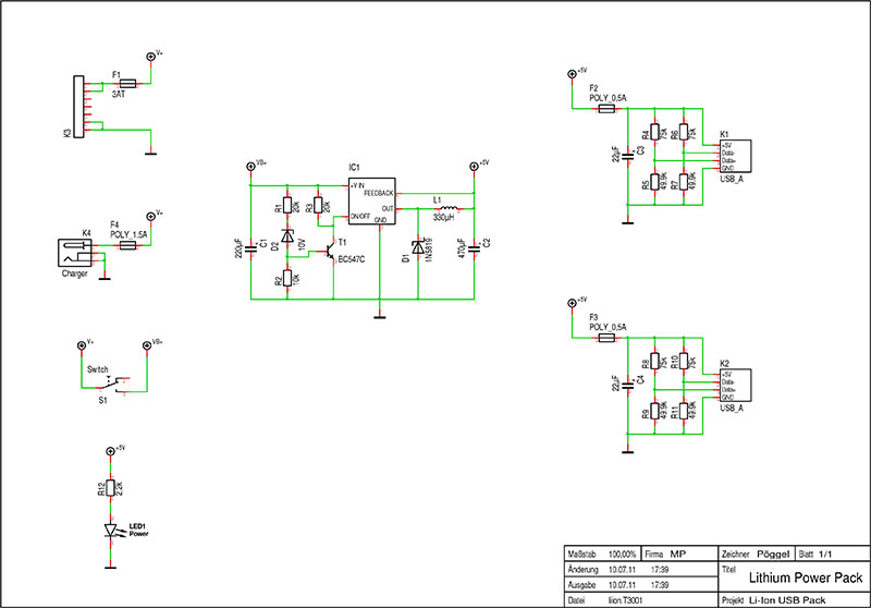
Voltage dividers consisting of two resistors are connected to the data lines of the USB ports. The reason for this is that many manufacturers identify their USB chargers by the voltage levels on the two data lines. Adafruit Industries did a good job here - after disassembling and measuring an Apple® charger, I found out that it puts out a voltage of 2 volts on D+ and D- to signal the phone that it can be charged with 500mA. I used these resistance values, of course the whole thing is also compatible with any other USB chargeable device - for example my 4G Systems OneTab® or the Motorola Defy® etc.
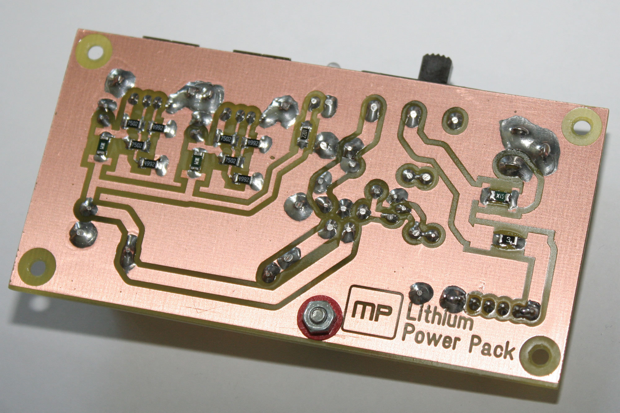
The backside of the board is not very exciting. Depending on availability, the fuses can be installed in SMD 1206 or large 2016 / Schurter OMT packages.
As storage choke for the switching regulator I used a 77A 330μH interference suppression choke from Fastron. It is capable of delivering sufficient pulse currents. If you want to increase the efficiency even more you can also wind a T106-26 Amidon ferrite core with 60 turns of 0.7mm CU enamelled wire (a little over 2m long). There is enough space for mounting it with an adhesive pad.
Technical data
- Battery power: 65Wh / 14,8 Volt
- Output power: max. 5W (2x 5V / 500mA) short circuit proof
- Efficiency: 75-85% at 500mA to 1A load
- Current consumption: Idle 7mA, Undervoltage cutoff: 200μA
Downloads
Related links
The brand names mentioned in this article are property of the respective owners.