Night Vision Device
DIY Night Vision Device with IR Spotlight and CMOS Camera
In order to be able to move around in the dark without being seen or stumbling over something, I created this little fun project: A simple night vision device. It uses the fact that infrared light is invisible to the human eye, but CMOS or CCD camera modules are very sensitive in this range, if no IR filter is installed (color camera module).
Professional devices use so-called residual light amplifier tubes and thus do not need an infrared illuminator. However, such tubes are expensive, difficult to obtain and have a limited lifetime. For this reason I use a black and white CMOS camera module with 0.5 lux sensitivity which can be purchased for little money at well-known online auction sites.
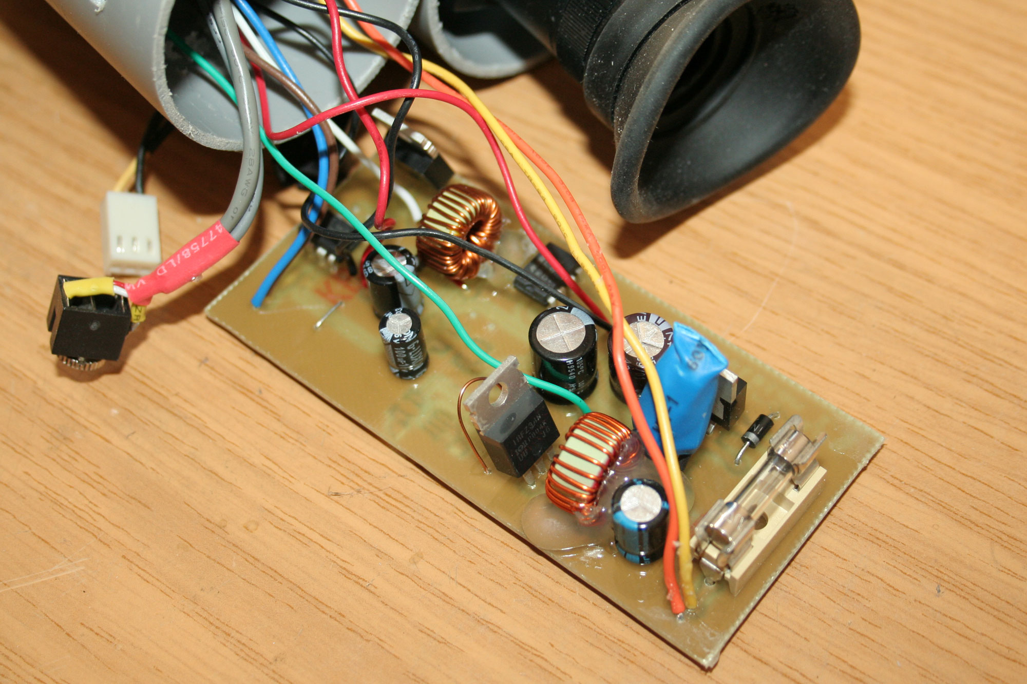
After first tests with different camera modules and infrared diodes, the demand for a suitable monitor came up, which was supposed to display the image signal of the camera module. I first thought of a small TFT display, but this reduces the portability and is not exactly inconspicuous in the dark because of the backlight. In my basement I found some defective VHS camcorders with CRT viewfinders. Immediately it was clear that these are best suited.
The viewfinders used contain a tiny cathode ray tube with 1cm diagonal screen size. Caution: On the circuit board there are several kV of high voltage and a few hundred volts for the deflection. Never touch the running setup!
Finding out the pin assignment from the viewfinder is a bit challenging. If the rest of the camcorder is still present and working, you can measure the voltage levels and video connections with an oscilloscope and multimeter. If not, it helps to have a close look at the layout (there might be capacitors where the operating voltage is) and to try it out carefully. In any case, use a lab power supply with current limiting to avoid destroying the viewfinder. Always turn up voltages slowly. If the deflection / image is too small the voltage is too low. If the tube is out of focus the high voltage and therefore the operating voltage is too high. In the two viewfinders I tested, one needs 9 volts and the other 5 volts. In addition, one of the two viewfinders could not handle the signal from the Conrad camera module (which is not very bright anyway). Apparently this is due to the reduced TV resolution. If the screen remains black, just try another video signal source. Useful camera modules can cope with 0.5 lux or less illumination, and are producing a high resolution of at least 500 TV lines.
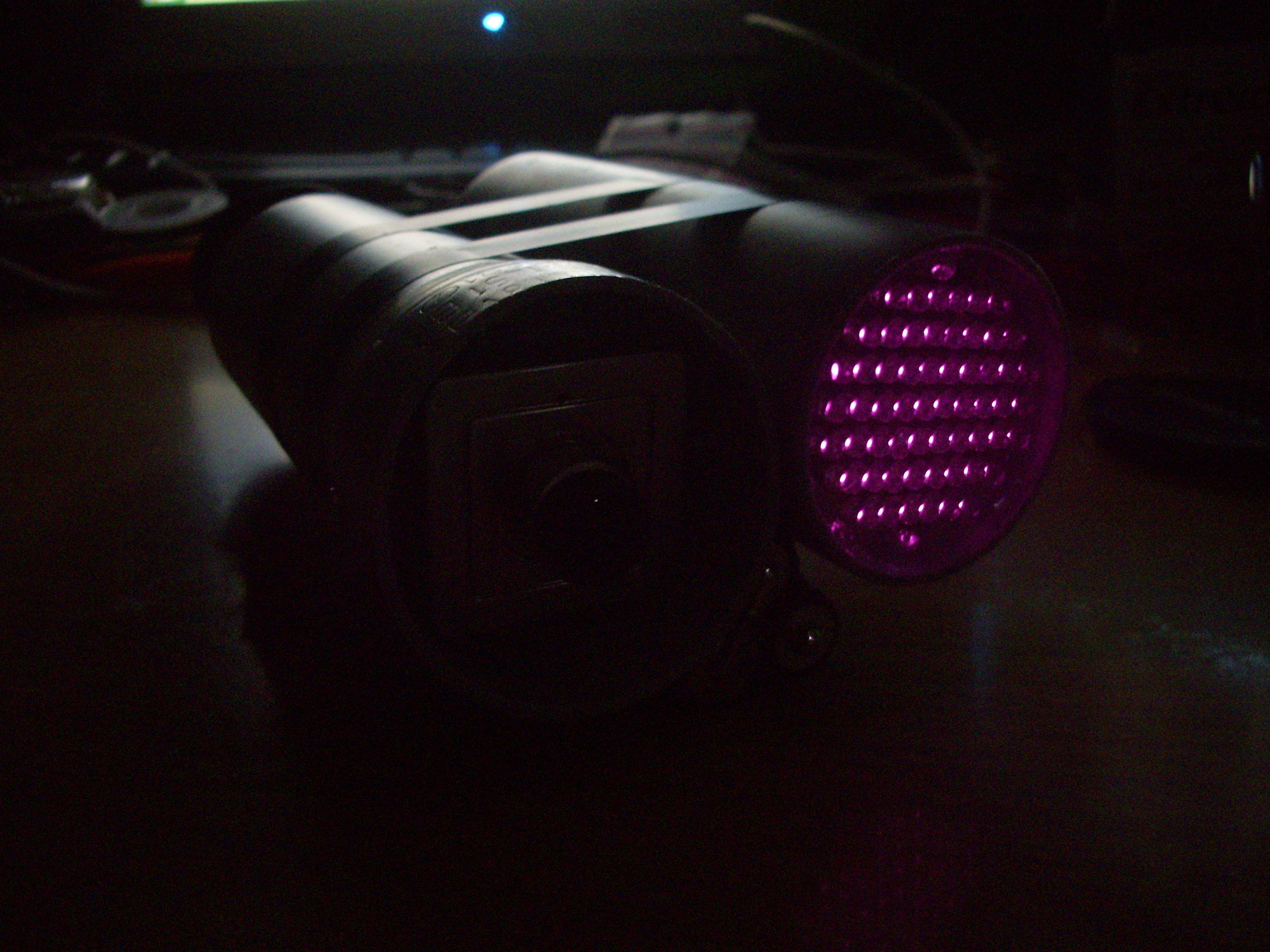
The next step was to find a suitable infrared source. Tests with different diodes showed that a very narrow radiation angle is useful. In the basement I found a handful of OPE5885, these have 850nm wavelength and a radiation angle of 17 degrees and an intensity of typically 40mW/sr. For sure there are better types out there, but I would have had to order them specially otherwise. The light output of the prototype is useable at least.
It is important that IR diodes reach their full power only in pulse mode, in this case at 1/100 keying with 0.1ms length and 0.5A(!) pulse current.
This keying is done with an Atmel microcontroller, which also monitors the battery voltage and alerts the user by a red LED in the viewfinder and later deactivates the LEDs completely to save the batteries.
This also leads us to the next problem - the power supply. The viewfinder and processor run on 5 volts, the pulsed LEDs (partly in series) on 24 volts and the camera module on 12 volts. To stay as efficient as possible and to cover a wide input voltage range I combined three switching regulators here. The operating voltage can be between 6 and 10 volts without any problems. So both NiMh and Lithium cells are possible. Voltage thresholds and LED timing are software programmable in the source code of the controller.
Now let's have a look at the schematic:
The board layout is designed to slide into a 45mm tube. The viewfinder and camera are on one side, a second section attached to the first tube with M3 screws contains the control board and IR floodlight.
The compensation resistors are important for the IR floodlight, since LEDs could have deviating values due to tolerances and thus individual series circuits would be loaded more than the others and burn out over time. There are four by 15 LEDs with a 82 Ohm resistor connected in series. In total, 60 LEDs are installed.
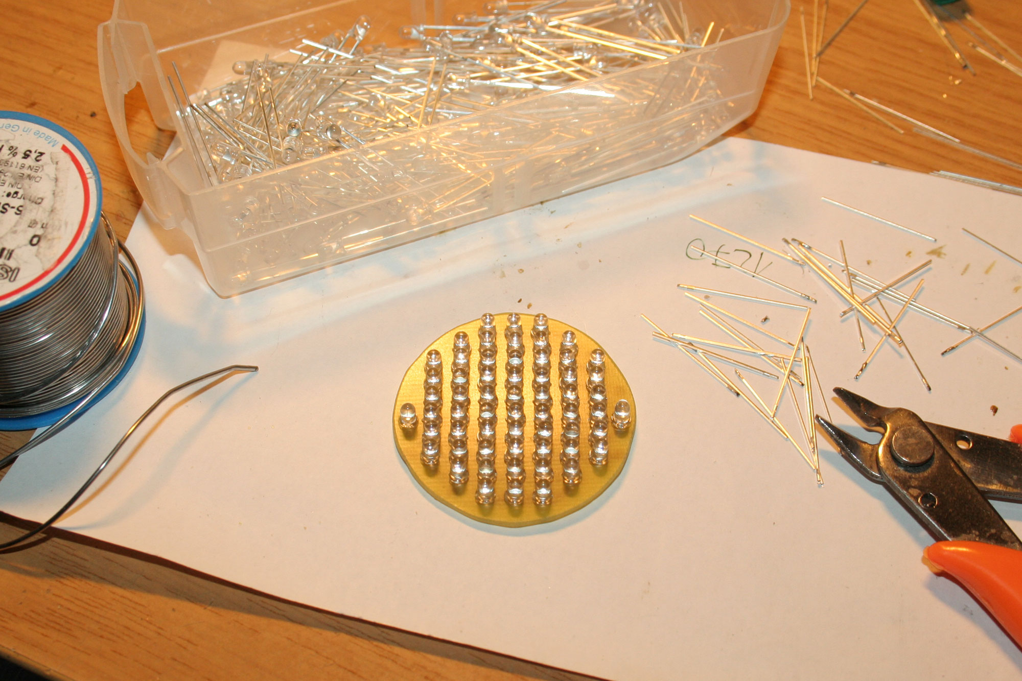
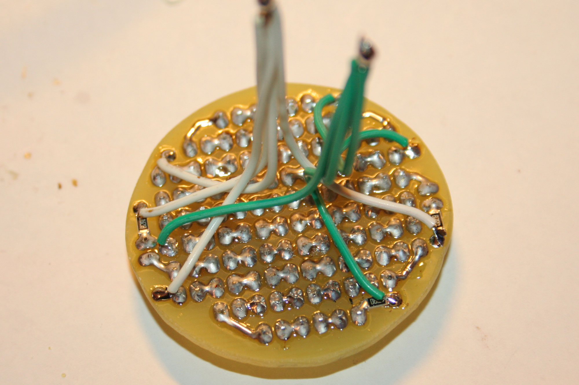
With a digital camera, the correct function of all LEDs can be checked perfectly. Please do never look directly into such a floodlight, as this could damage your retina permanently!
In the last step there is only the software left to be written. To keep the development time short, I quickly hacked it together in Bascom. There are about 40 lines of code for the ATTiny25. The internal 2.56V reference is used for voltage measurement. The keying is generated by Timer0 via PWM.
$crystal = 1000000
Config Portb.0 = Output
Config Portb.3 = Output
Config Portb.4 = Input
Config Timer0 = Pwm , Compare A Pwm = Clear Up , Prescale = 1
Ocr0a = 192
Dim Value As Word
Config Adc = Single , Prescaler = Auto , Reference = Internal_2.56_nocap
Start Adc
Do
Value = Getadc(2)
If Value < 390 Then
Set Portb.3
Waitms 500
Reset Portb.3
Waitms 500
End If
If Value < 340 Then Goto Poweroff
Loop
Poweroff:
Ocr0a = 255
Set Portb.3
Do
Loop