Talking alarm clock 1
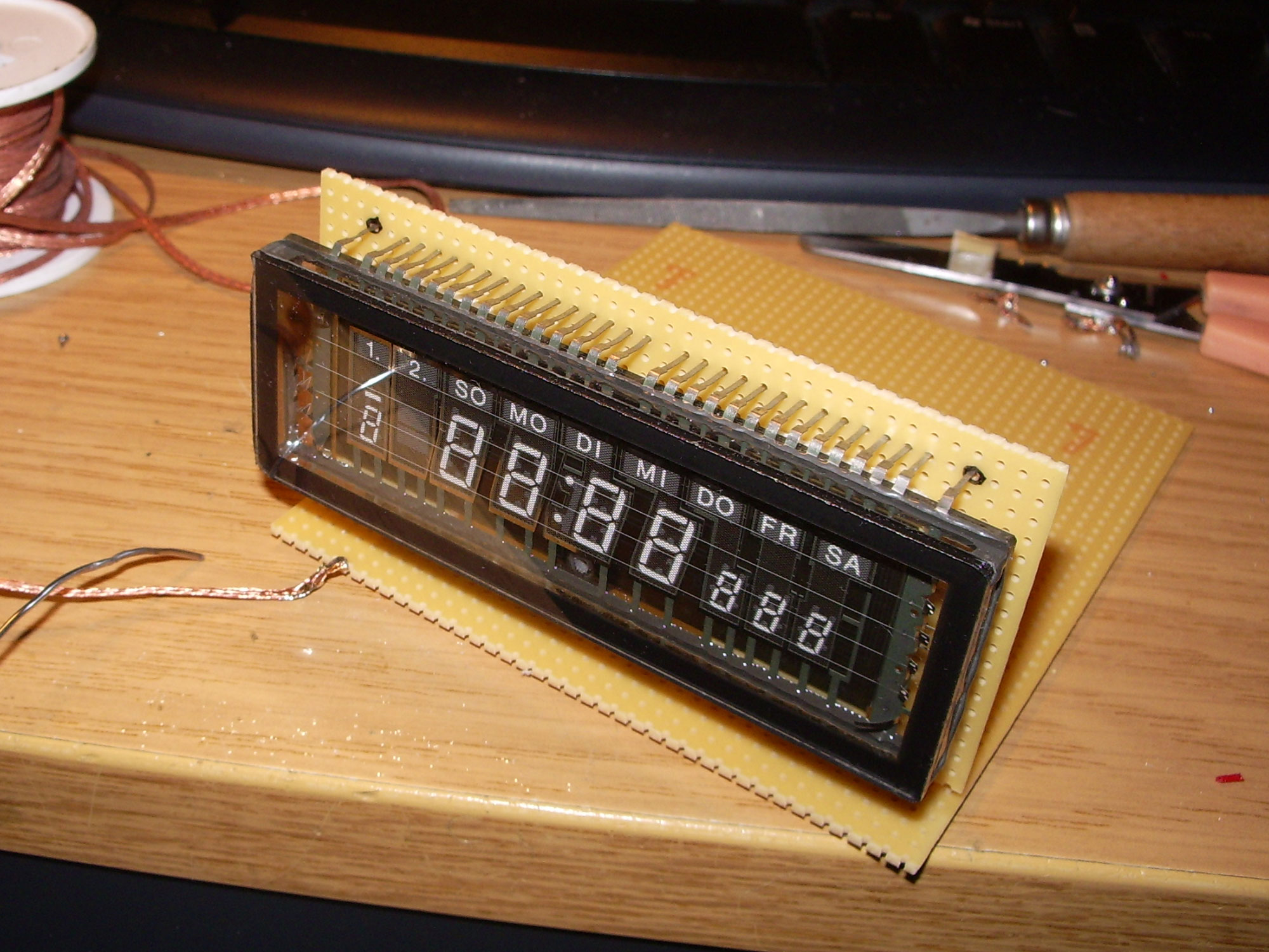
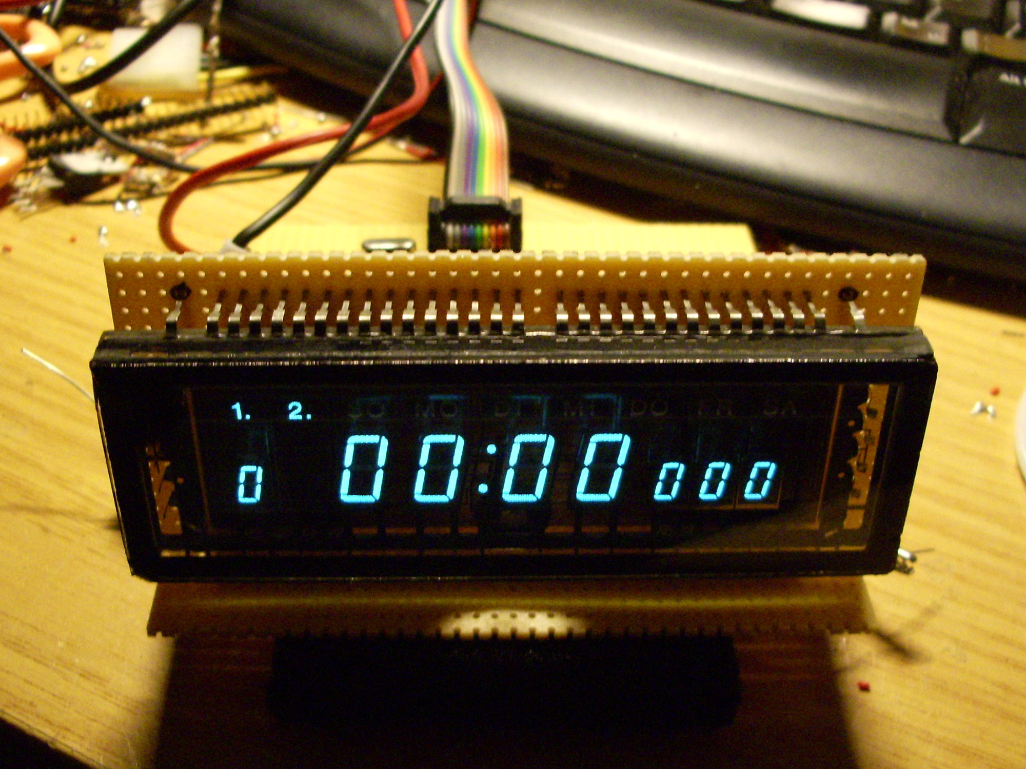
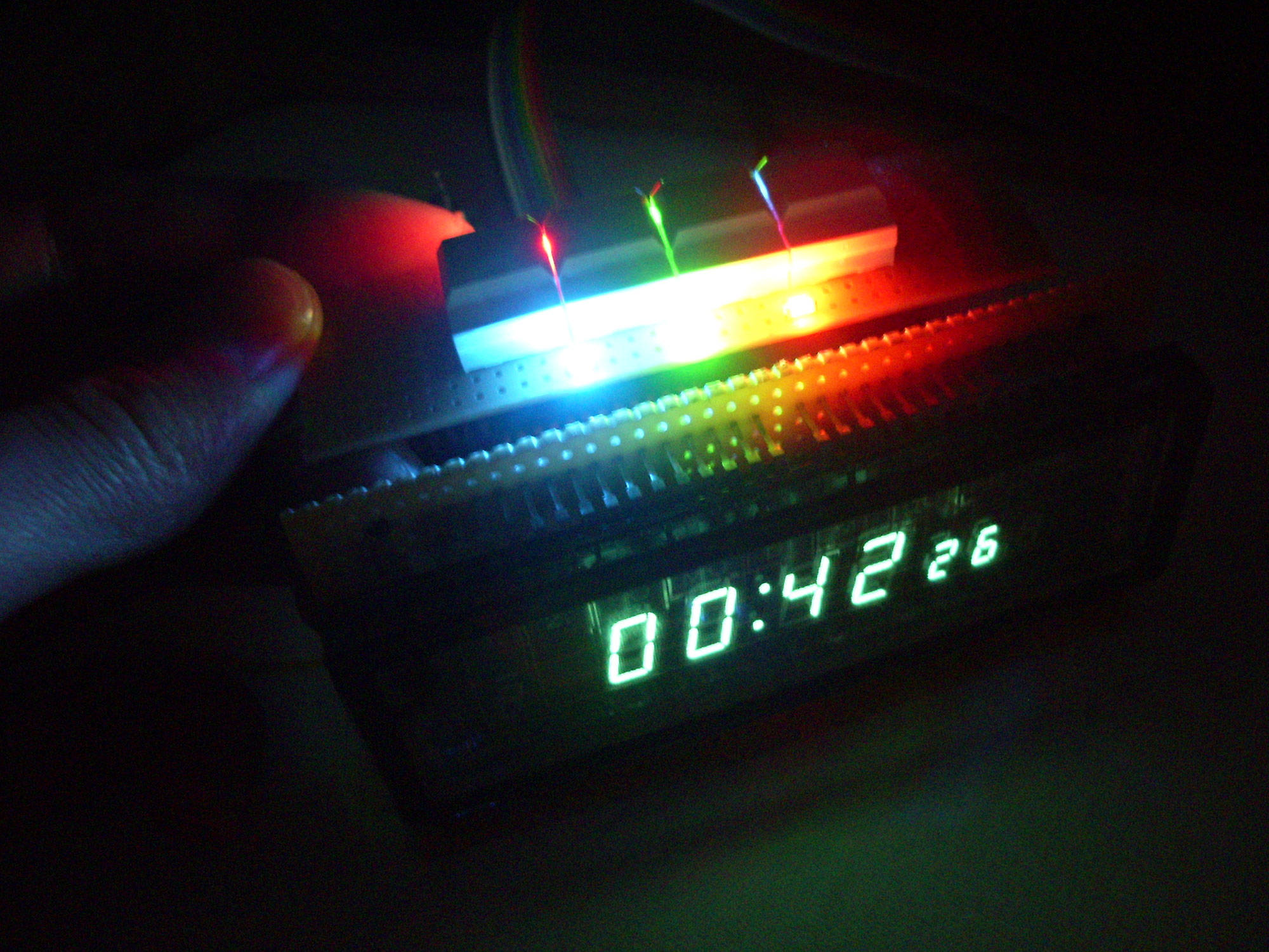
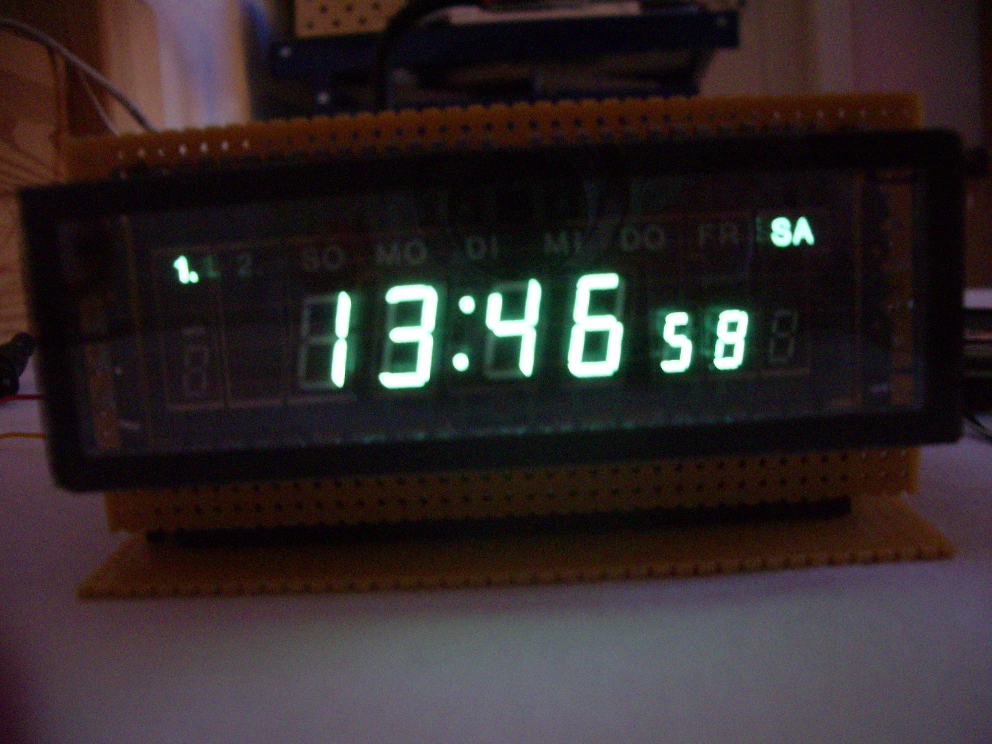
First version of the talking alarm clock with a vacuum fluorescence display
From a video recorder I had scavenged a vacuum fluorescent display, which was much too good to lie around in the tinkering box. For this reason I decided to build a decent alarm clock for my bedside table.
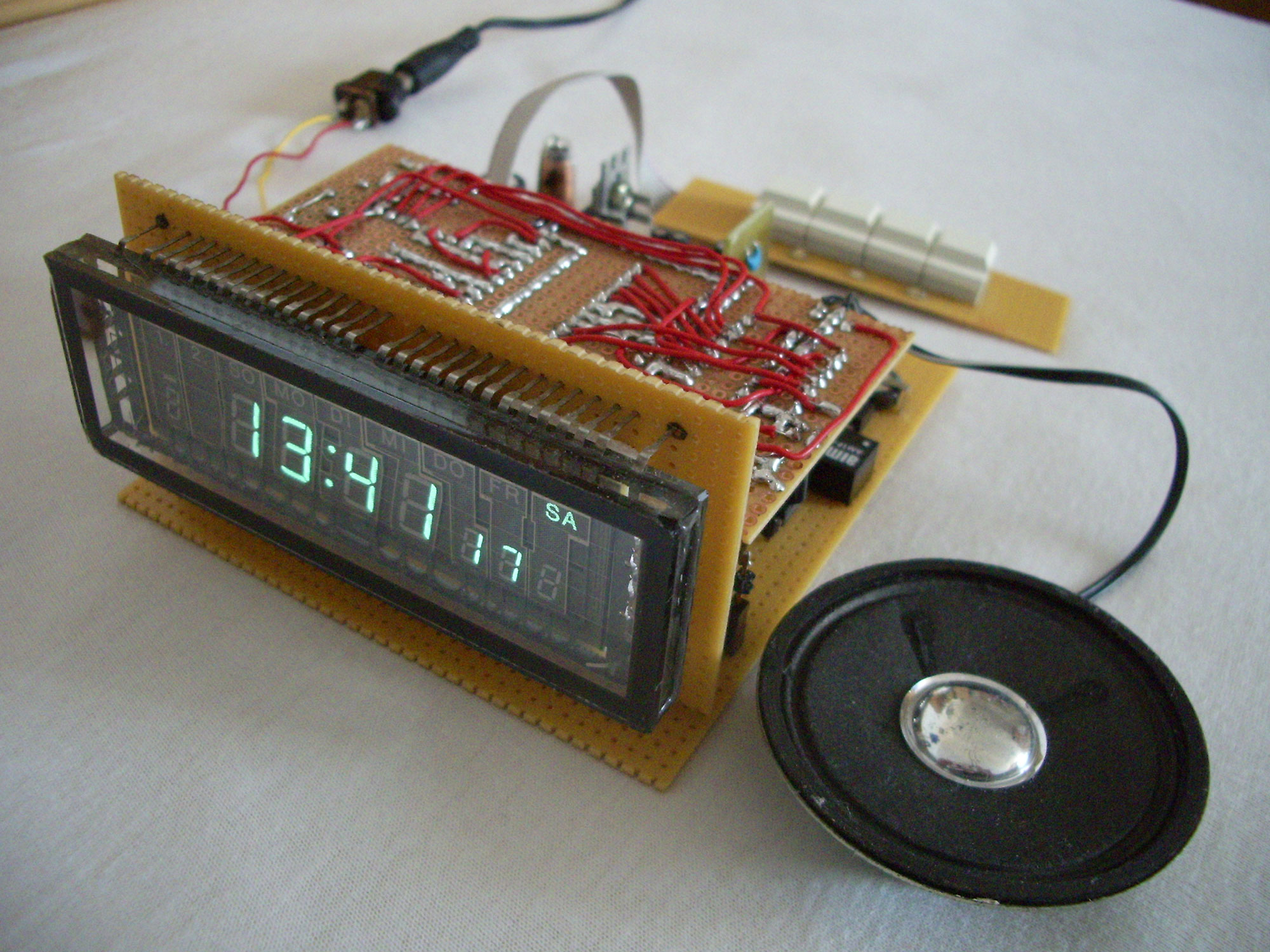
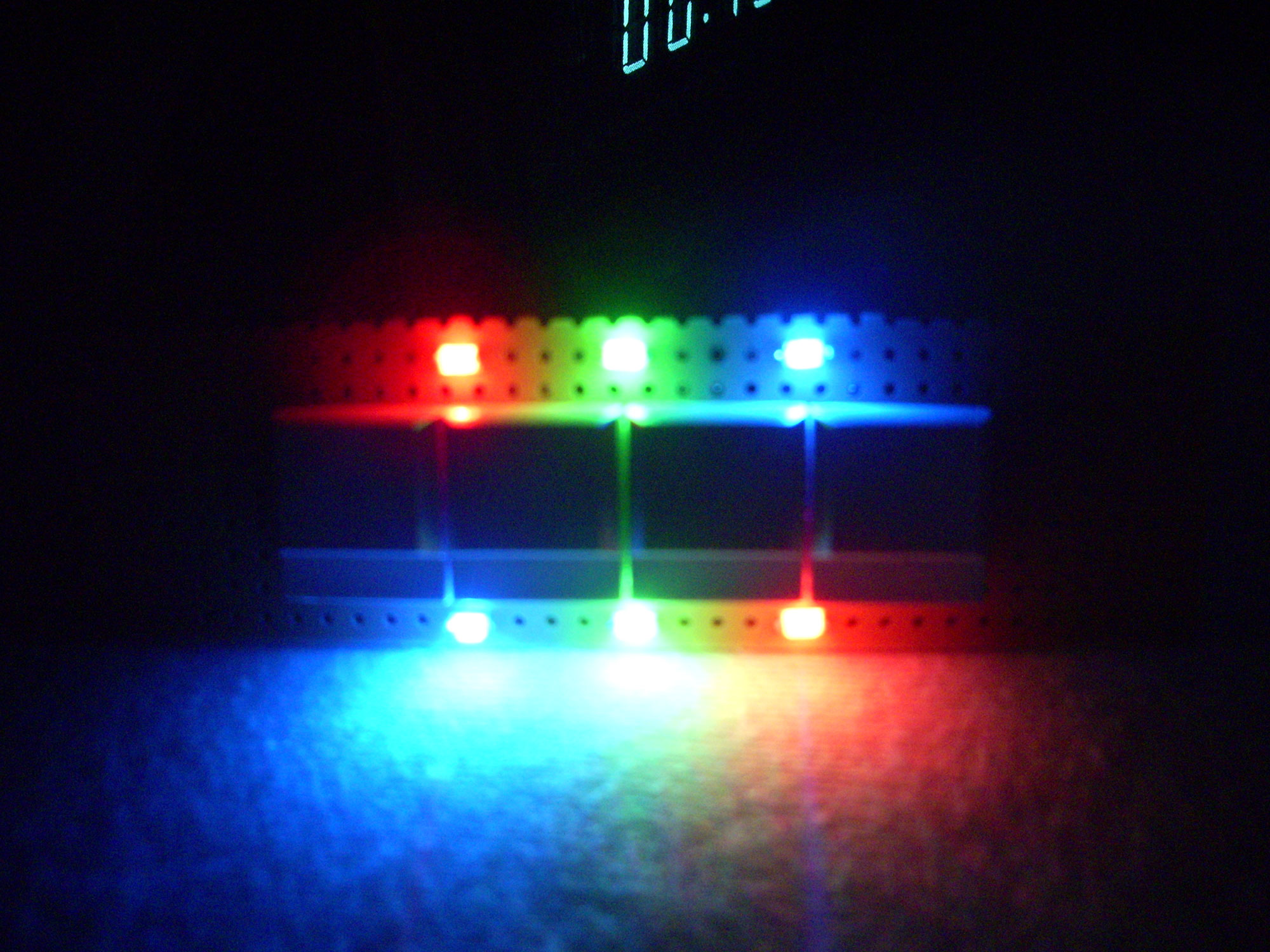
The functionality includes display of time, two independent alarm times, time announcement by voice, temperature display, 10 selectable alarm tones and optical alarm with RGB LEDs.
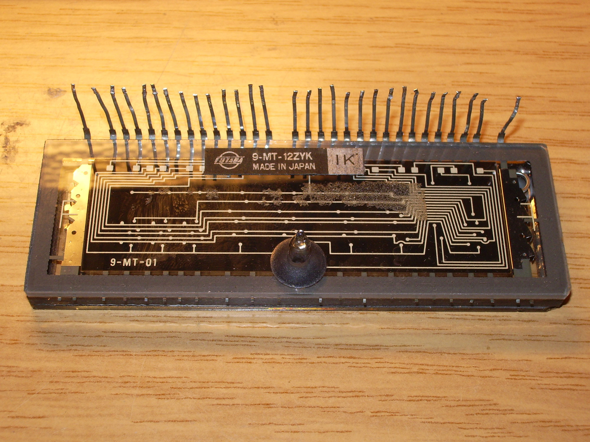
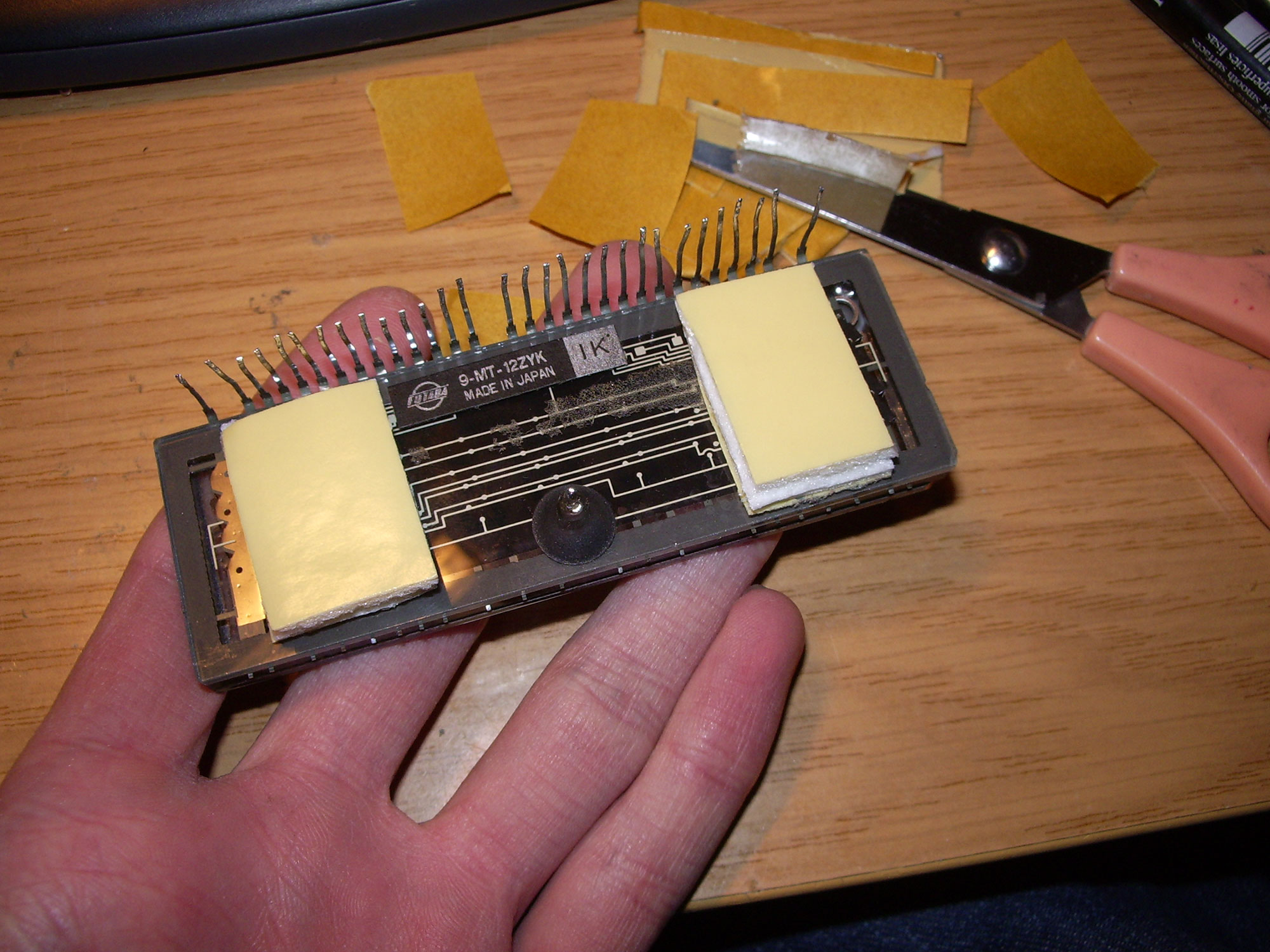
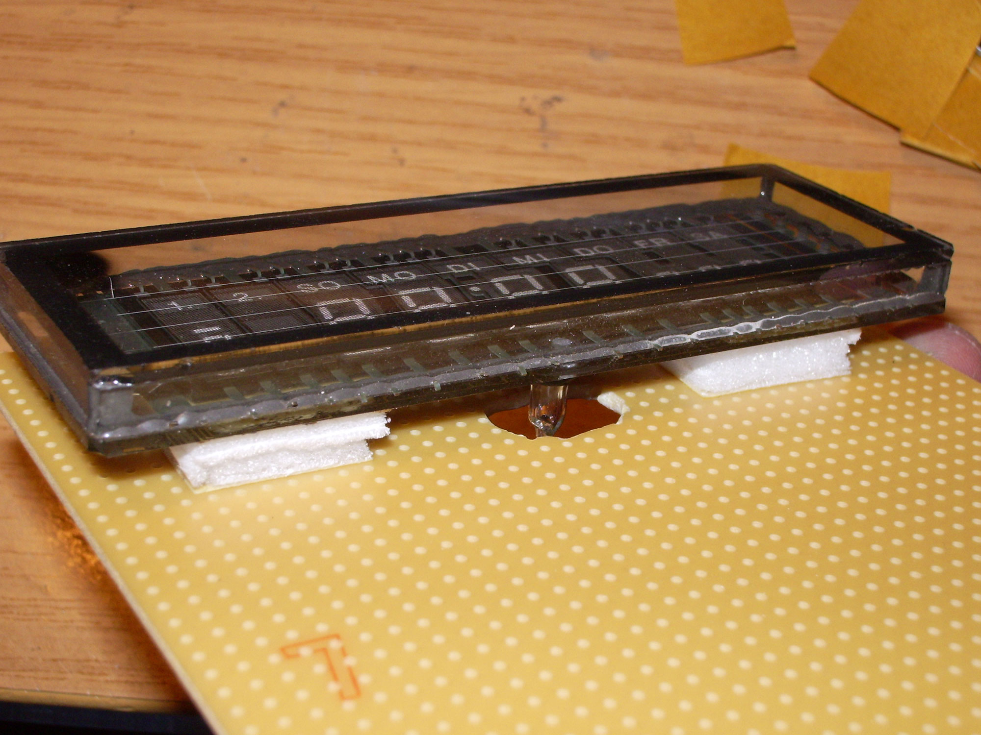
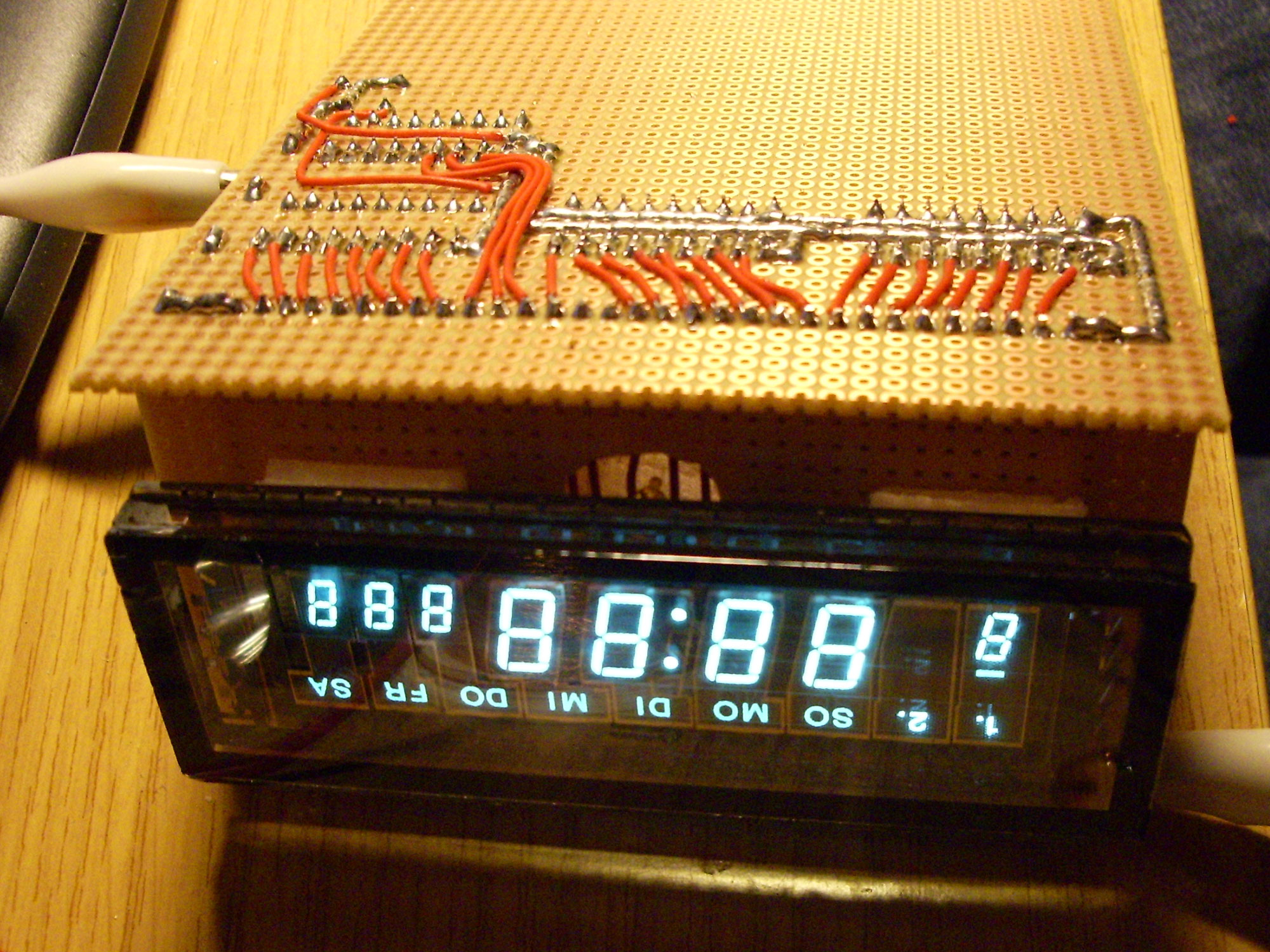
The assembly starts with the loose VFD.
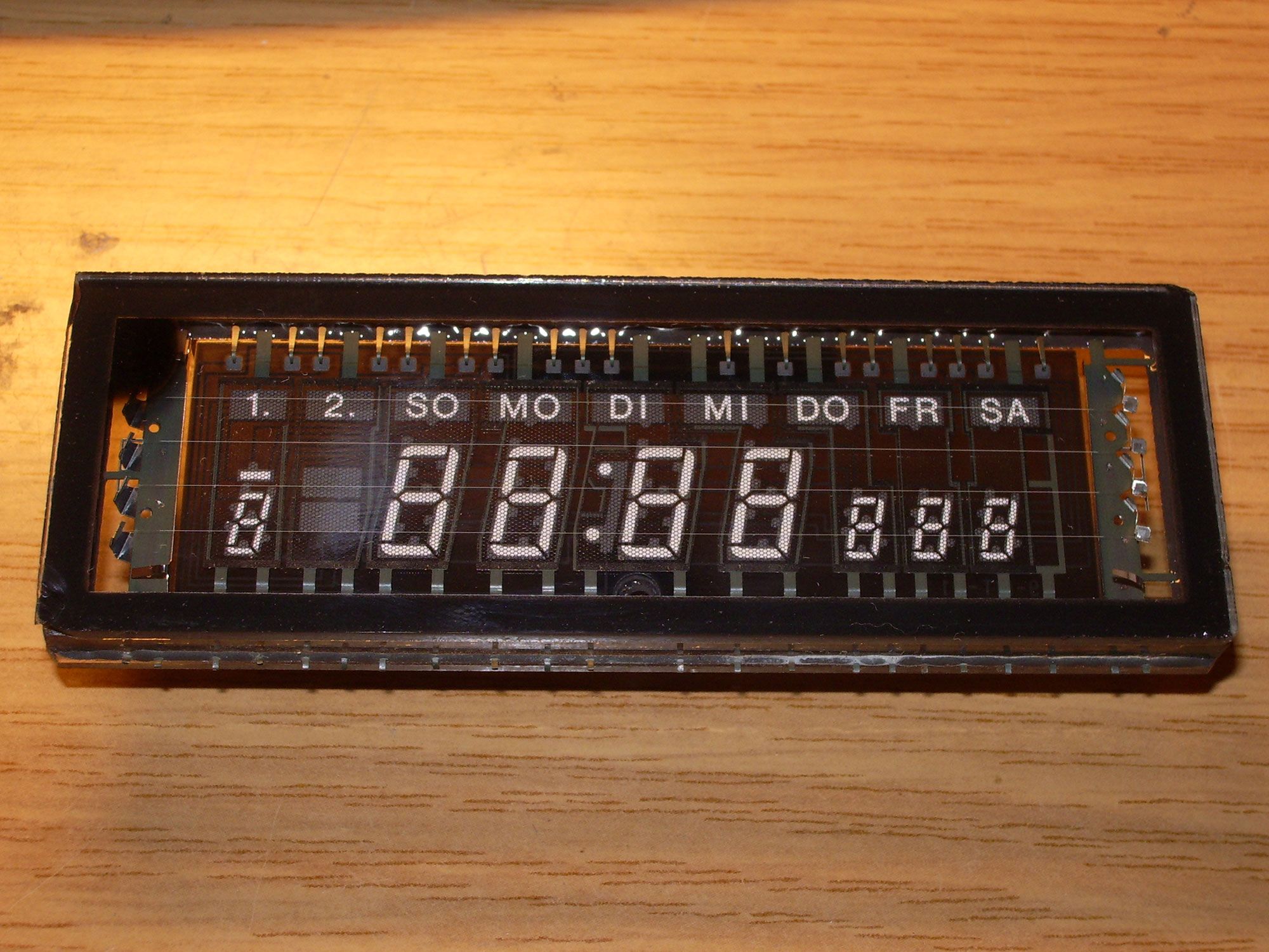
First the display has to be mounted on the board. For this purpose, a breadboard is used.
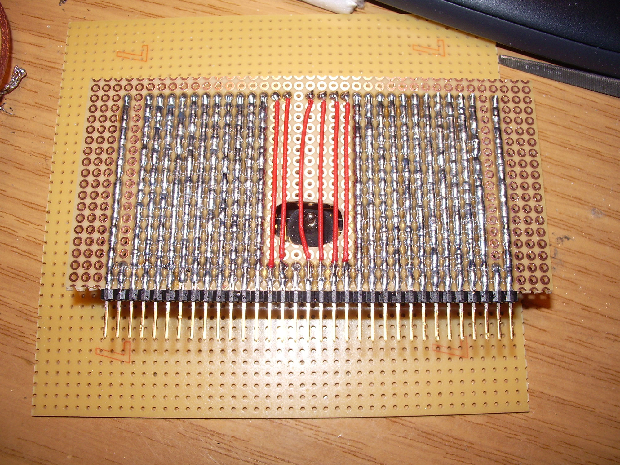
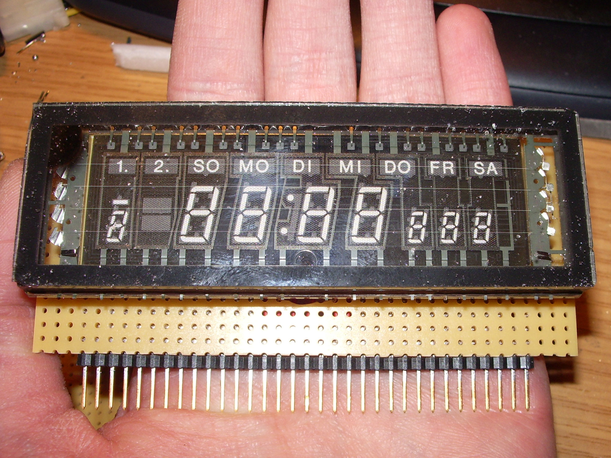
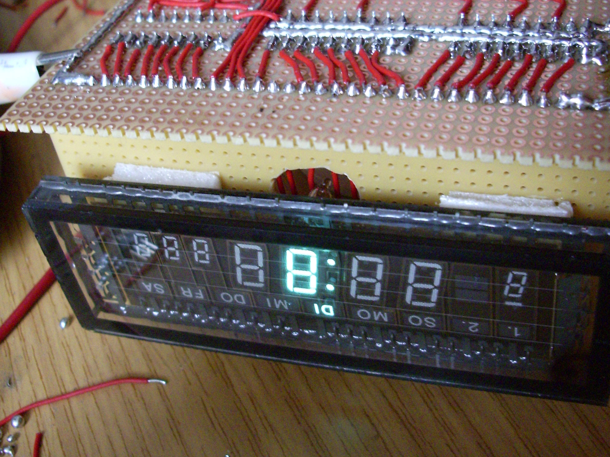
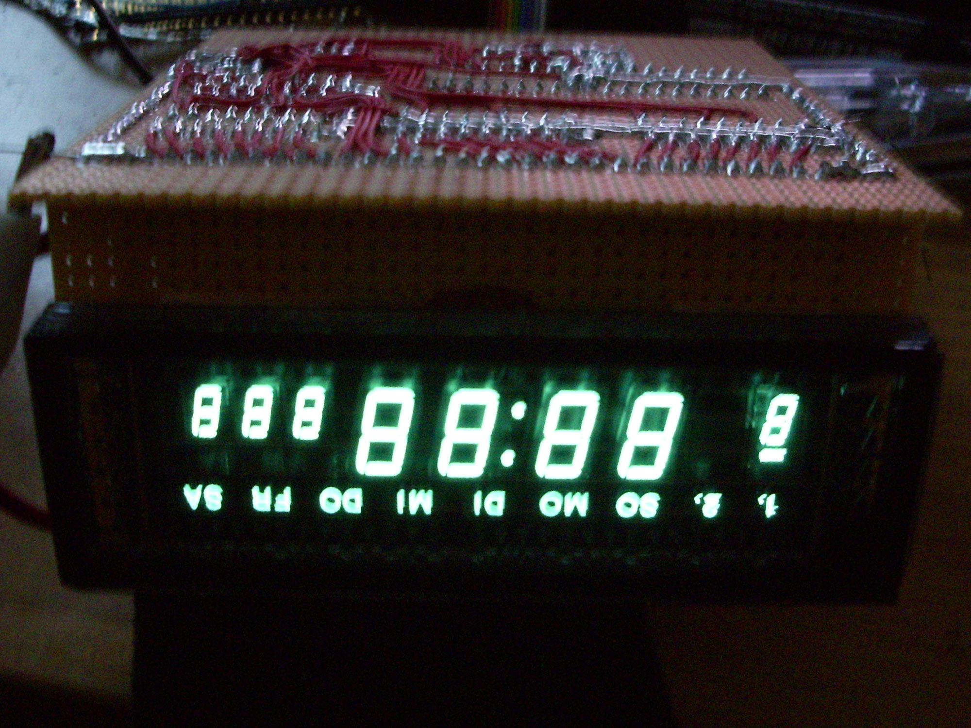
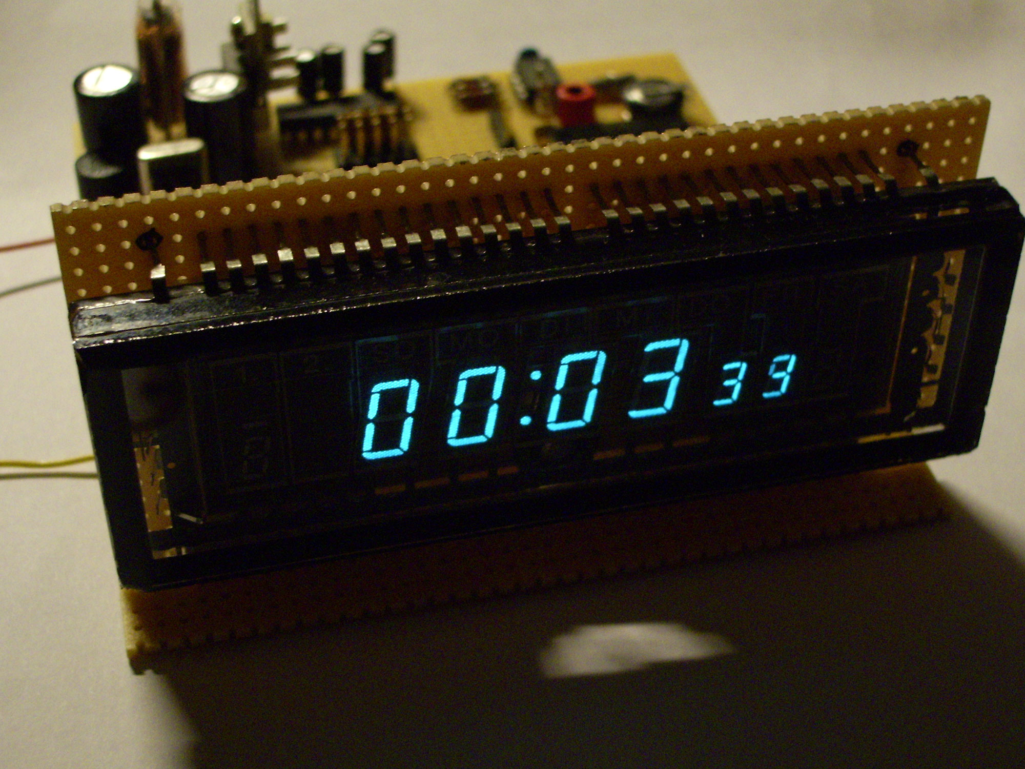
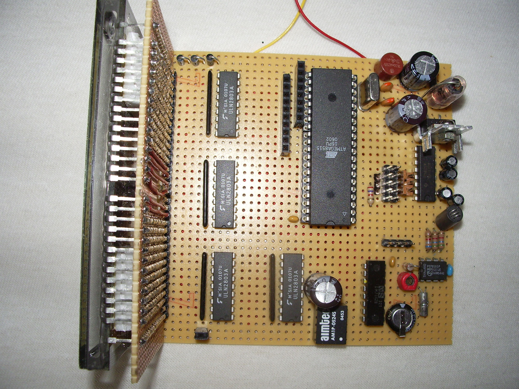
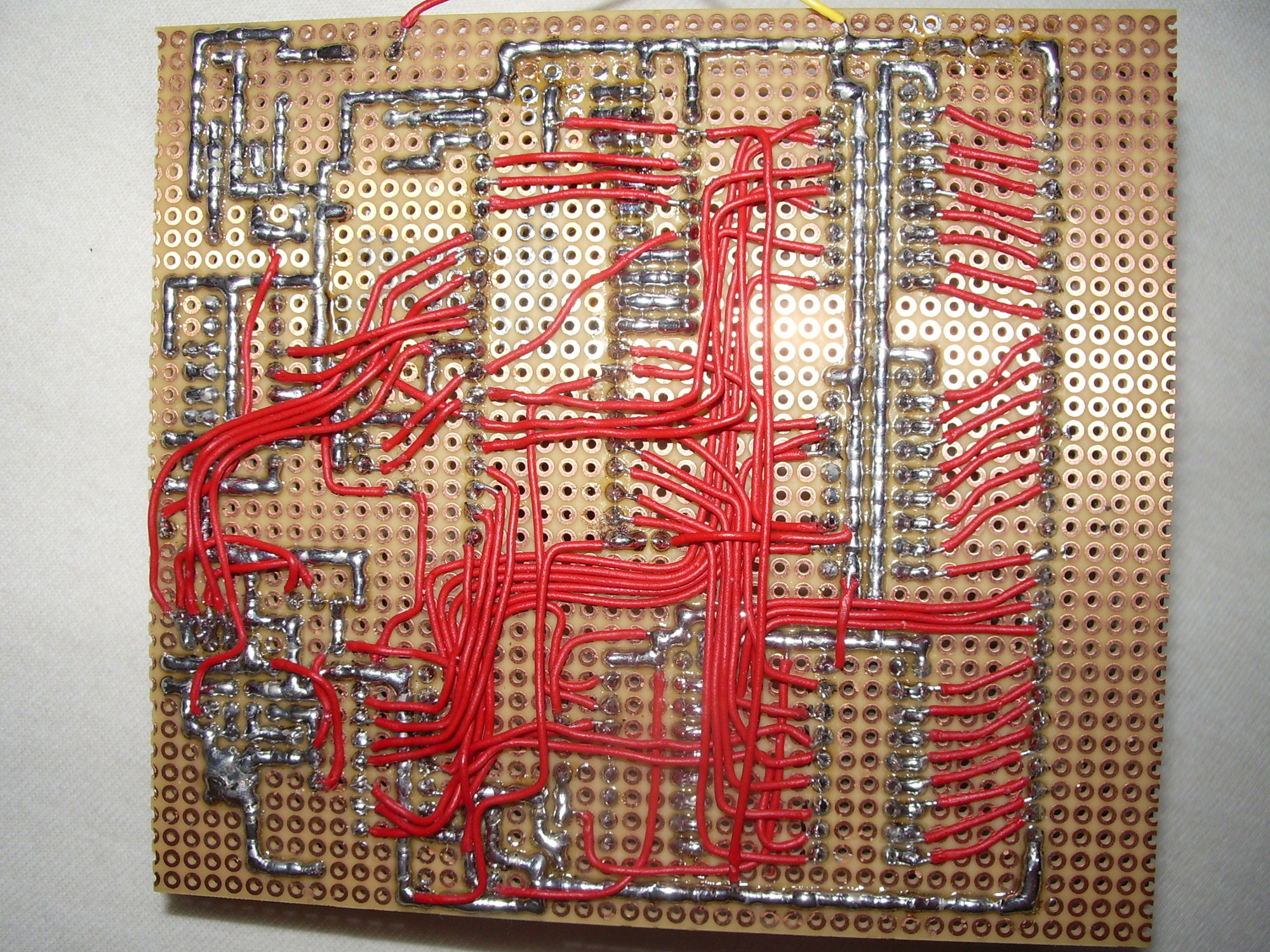
The display was mounted on a second PCB in a 90 degree angle. This board will be used as the main board later. Four ULN2803 with resistor networks are used as display drivers. These control the grids and segments of the VFD. The anode voltage of 24V is generated by a DC-DC module. If none of the transistors is controlled, all segments light up.
The upper left pictures show first setups with segment drivers, grid drivers and voltage generation. Top right and bottom row the test setup with multiplexing and AT90S8515 microcontroller. To drive the 9 grids with as few port pins as possible, a SN7442 1 out of 10 decoder is used.
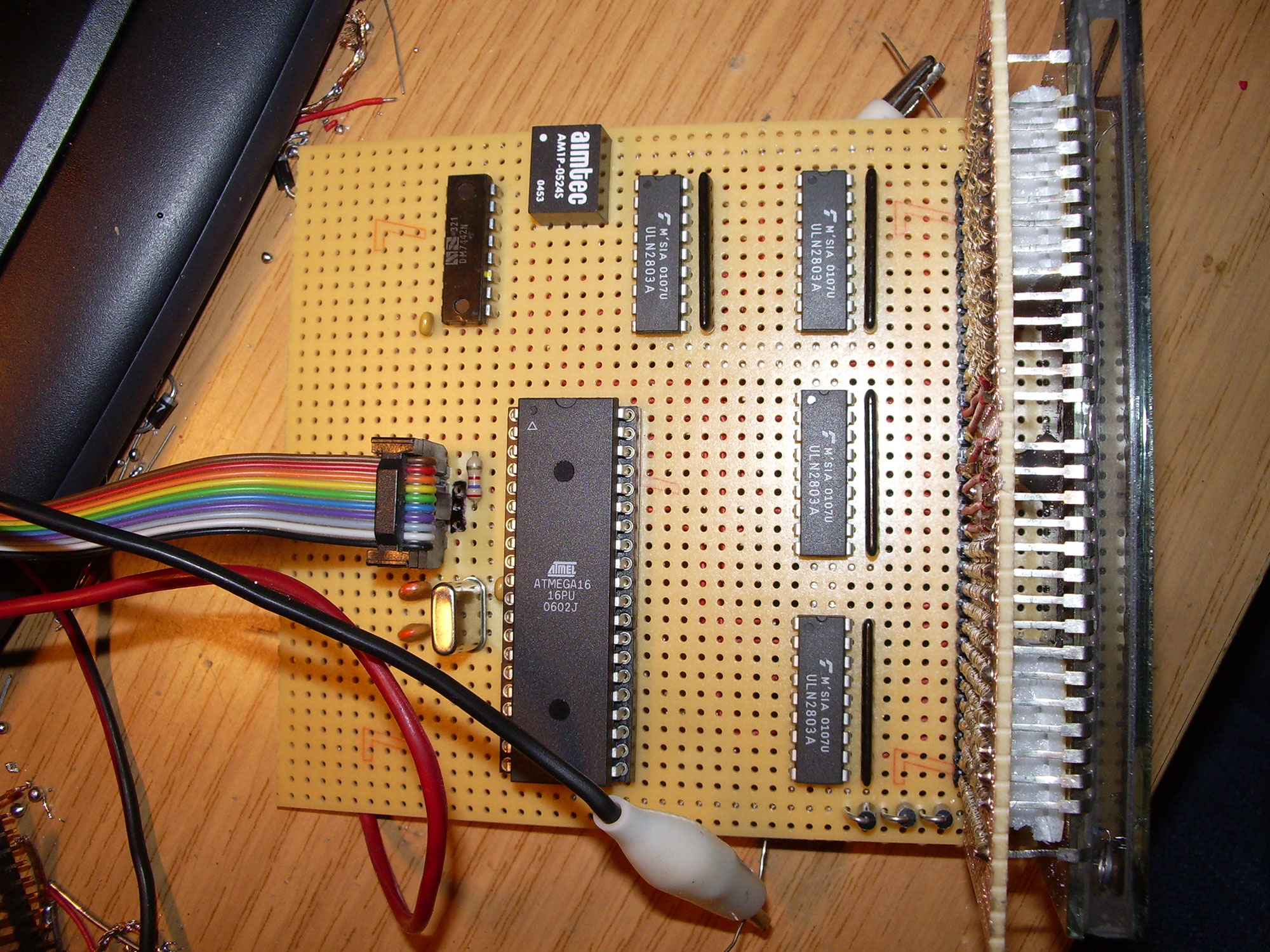
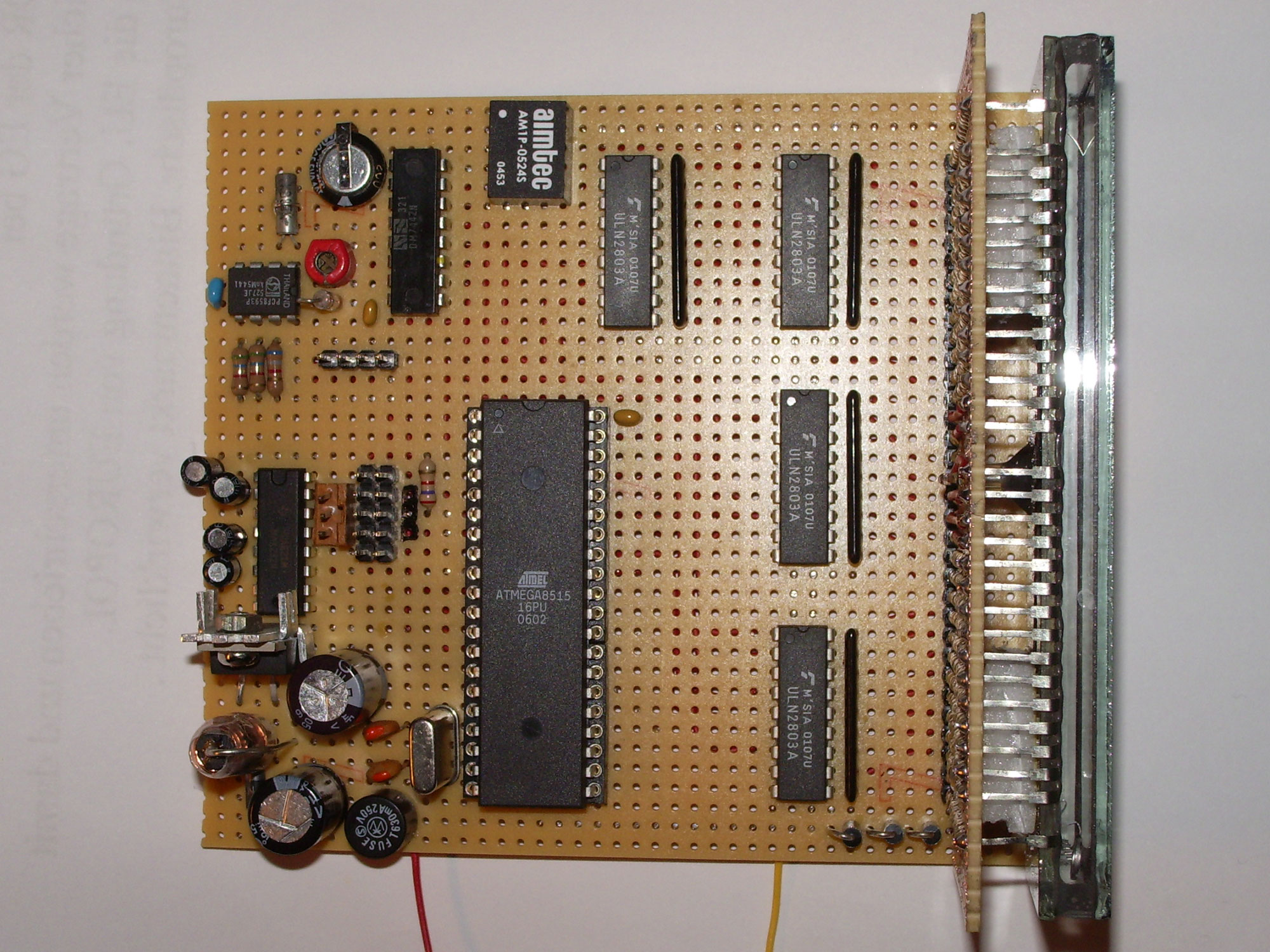
In the next step the PCF8593 realtime clock IC was installed. A supercapacitor keeps the operating voltage of the RTC during short power failures, so that the set time is not lost. The Atmel microcontroller communicates with the device via I2C. For easy debugging of the software, a RS232 interface with a MAX232 was also added. The generation of the 5V operating voltage is done by a LM2575 switching regulator.
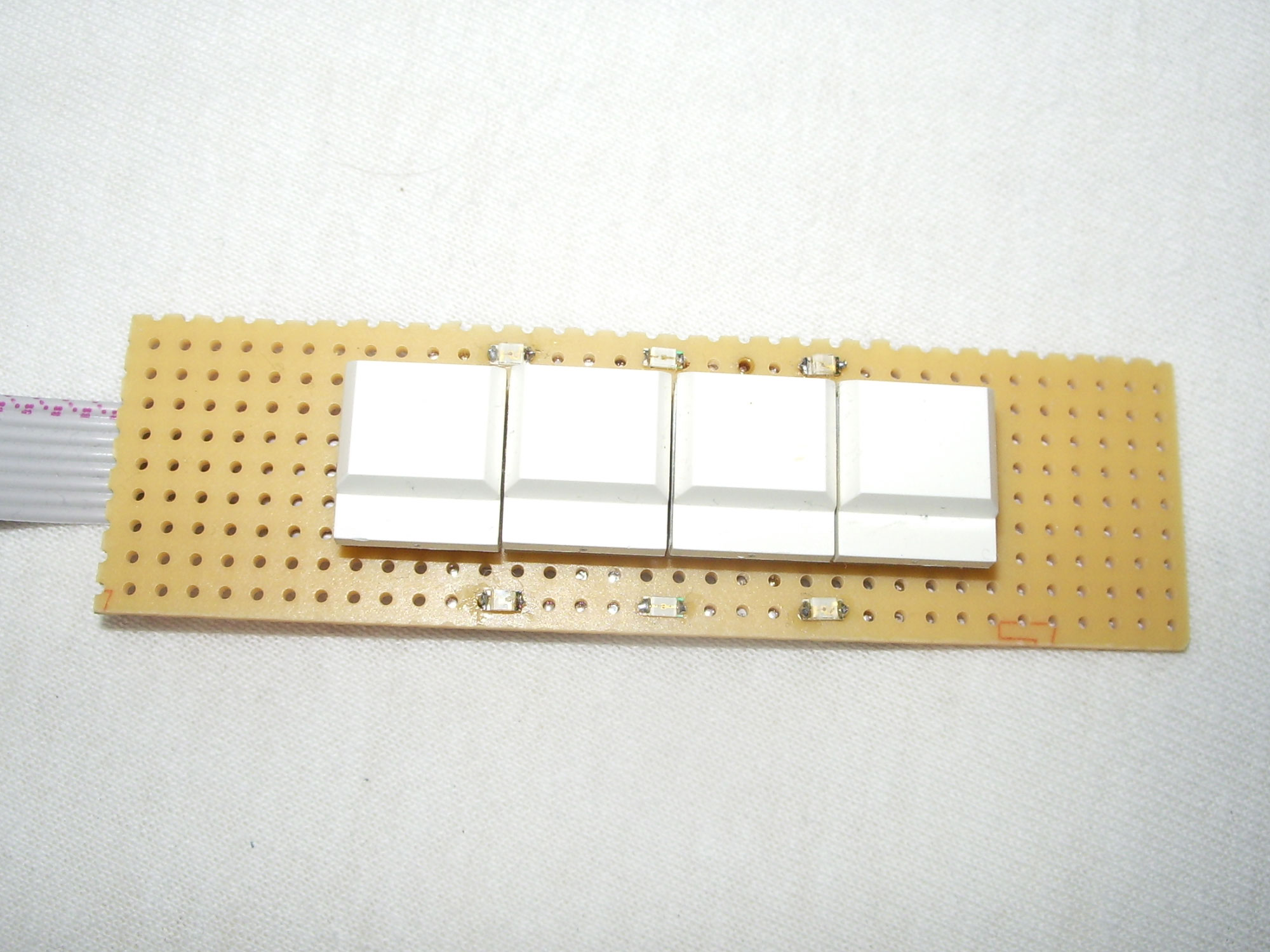
As an eye-catcher, two red, green and blue SMD LEDs were soldered on the key board.
The ISD2560 voice memory is mounted on a separate board. To save more port pins, two CD4094 shift registers were used. These control the address pins of the speech memory. As NF amplifier a LM386 is connected downstream. In standby it is switched off by a transistor.
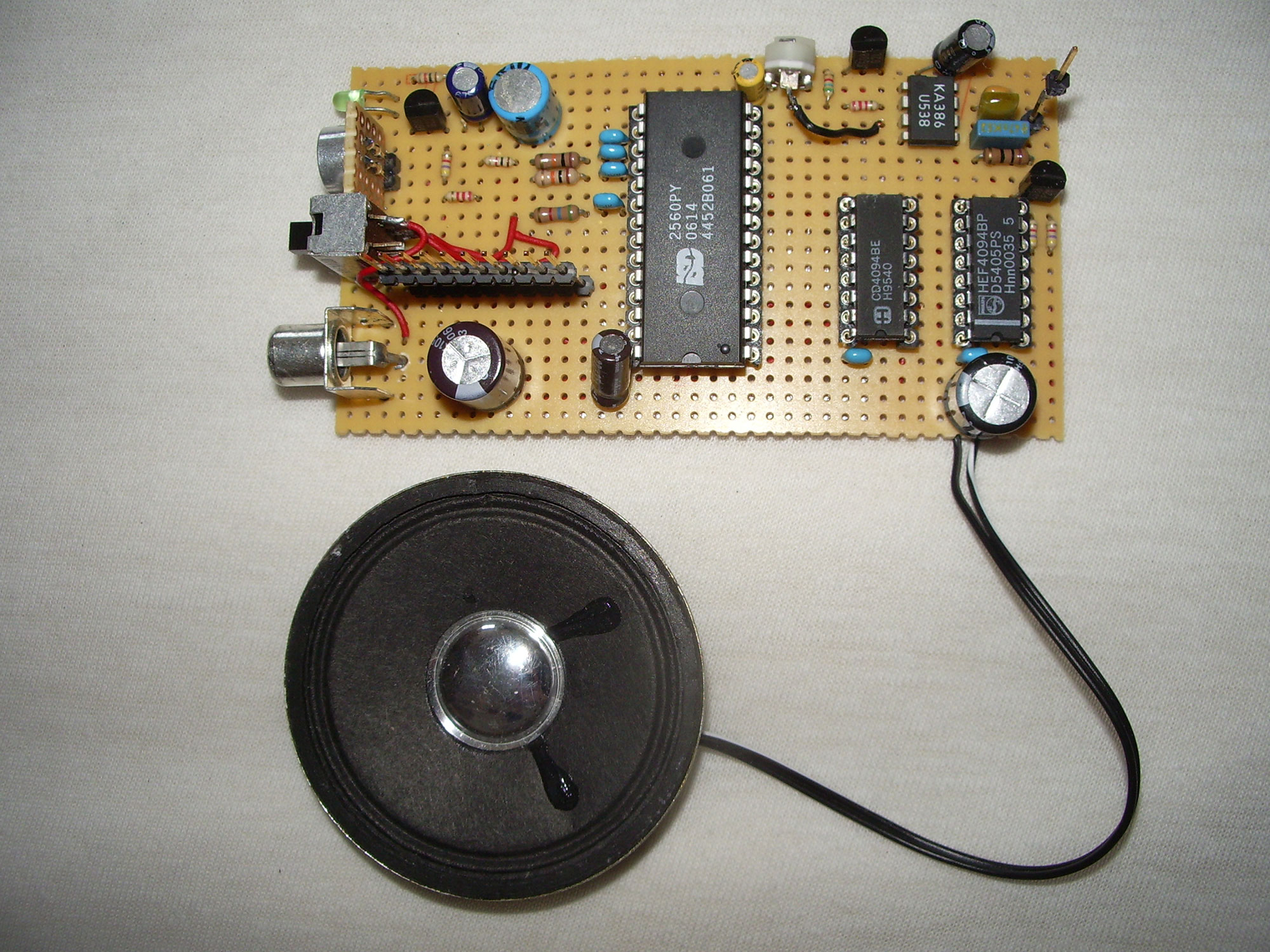
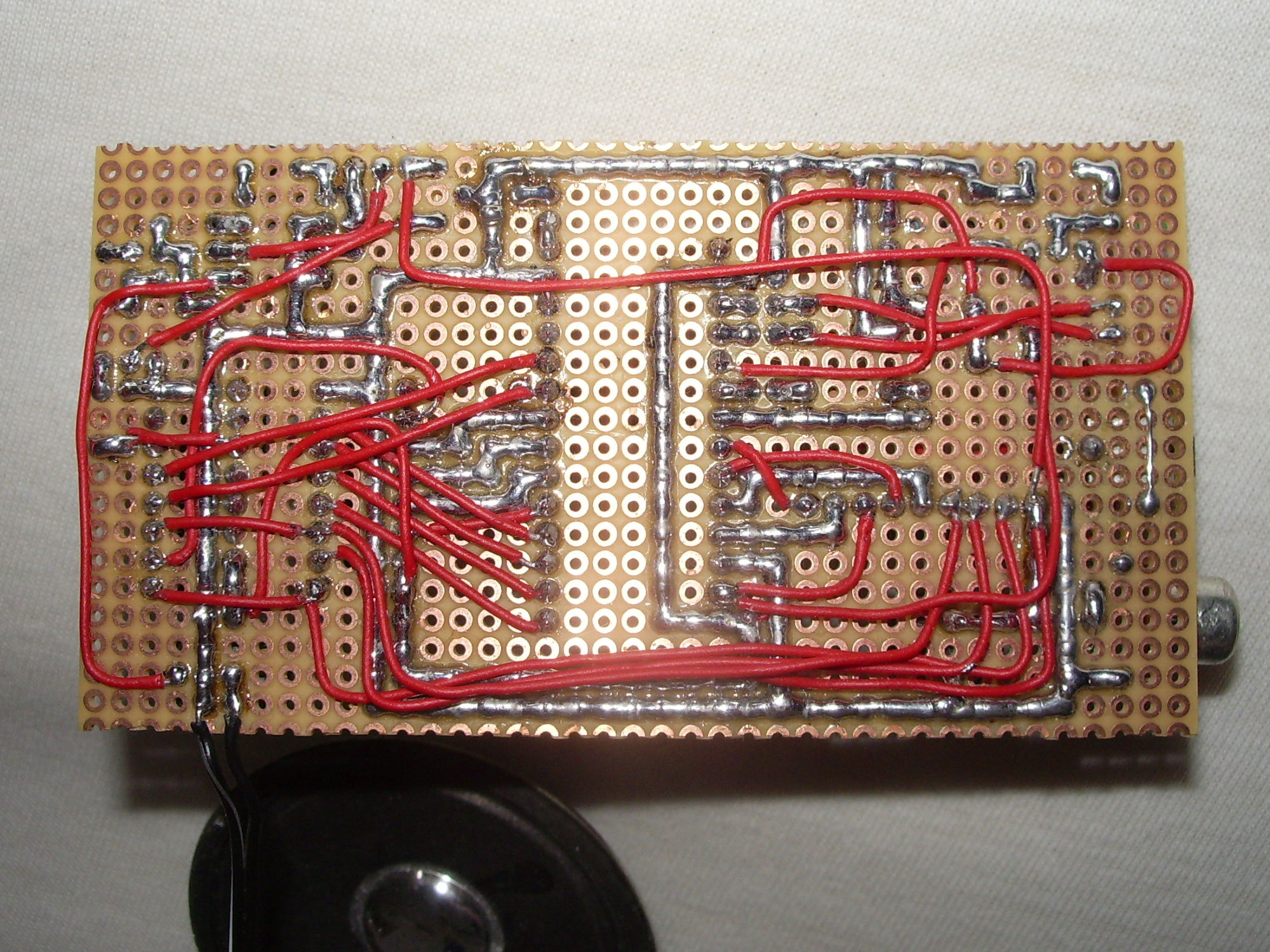
Finished main board
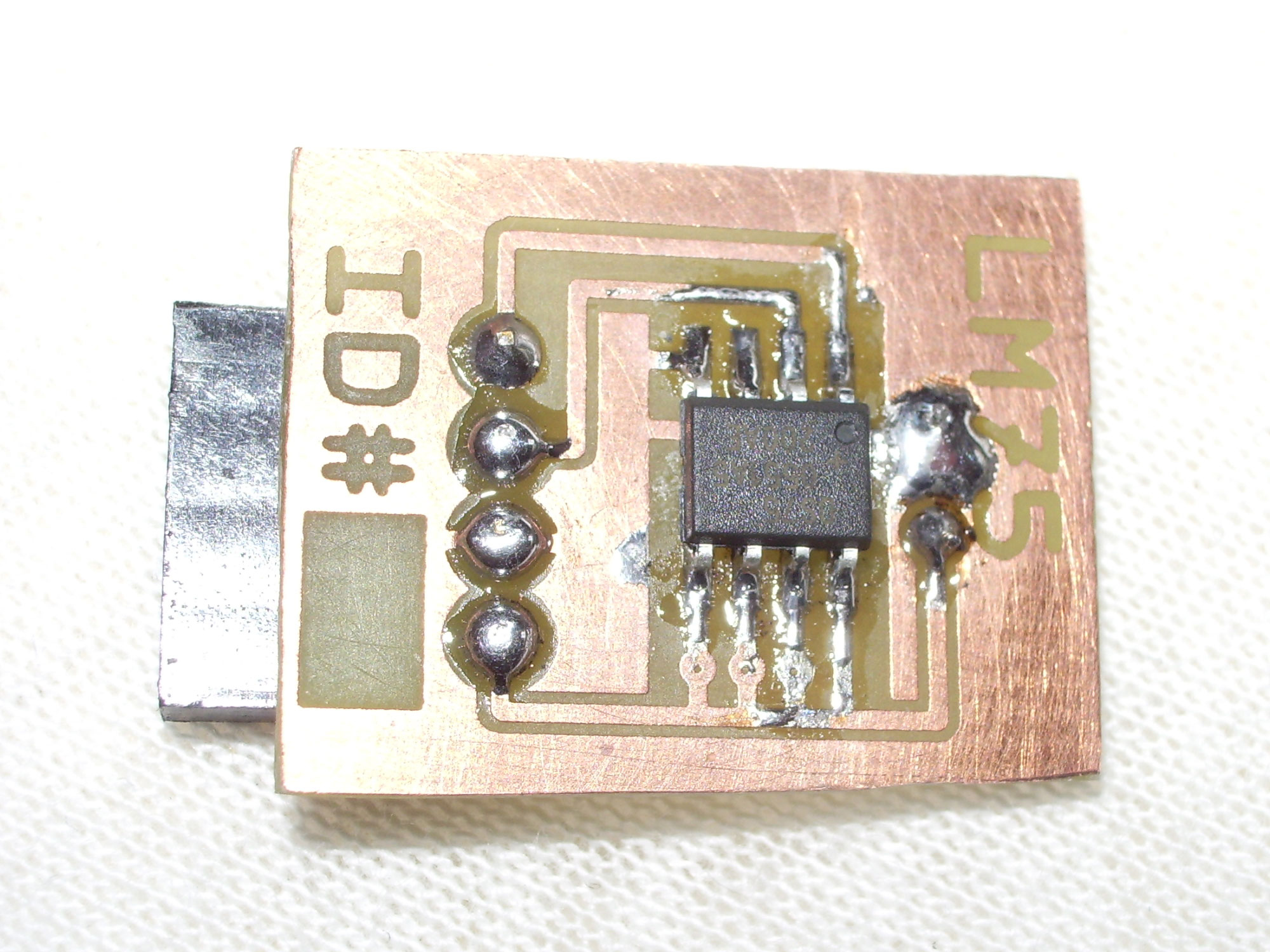
Keypad board and LM75 temperature sensor
Software
The software is written in Bascom. The keys can be used to navigate through different functions.
Menu 0
Display of time, weekday and if alarm 1, 2 or none is active
Time announcement at the push of a button
Activate alarm and switch between alarm times
Menu 1
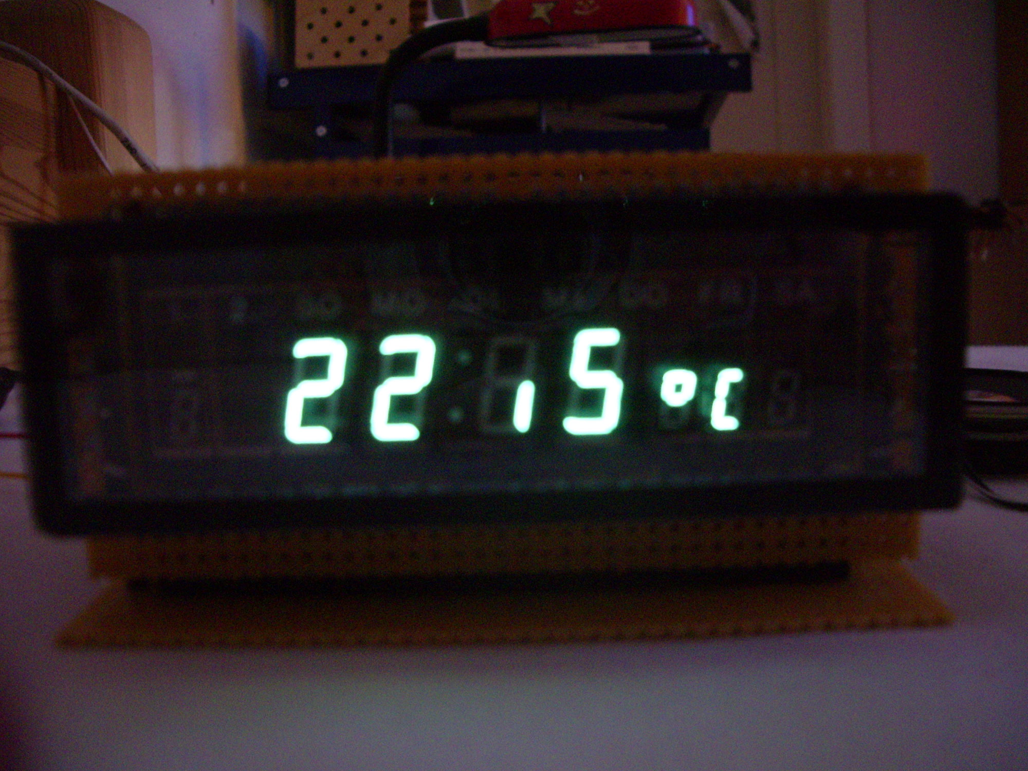
Display of temperature
Resolution 0.5 degree steps by LM75 I2C temperature sensor
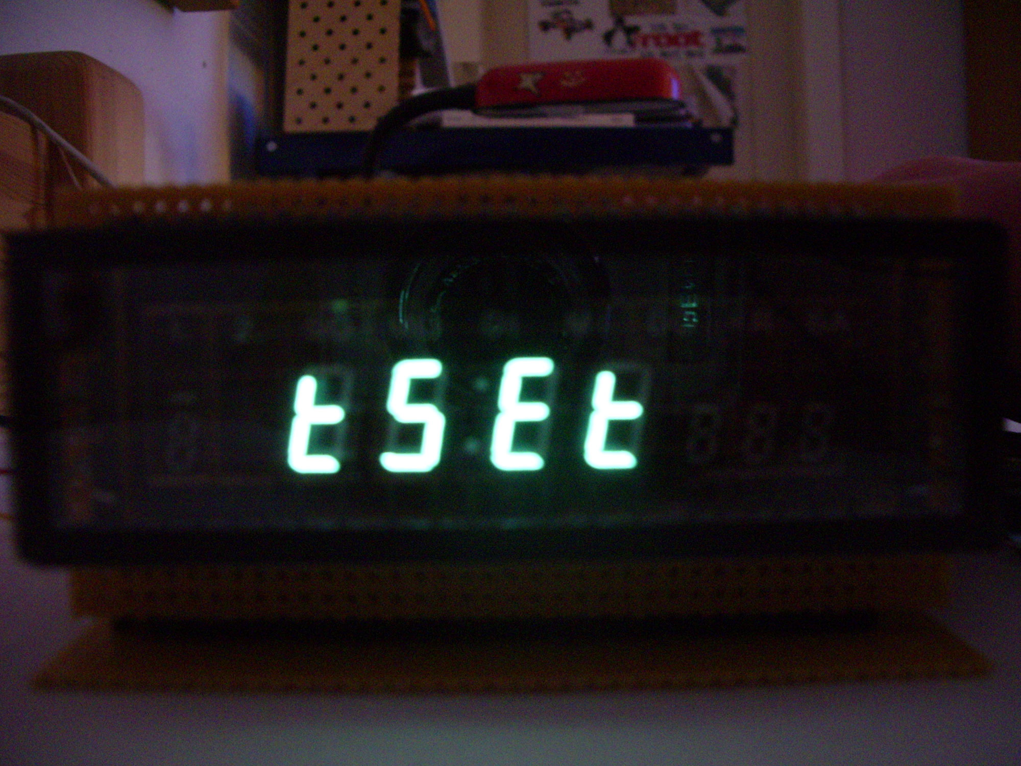
Menu 2
Time Set: Set time
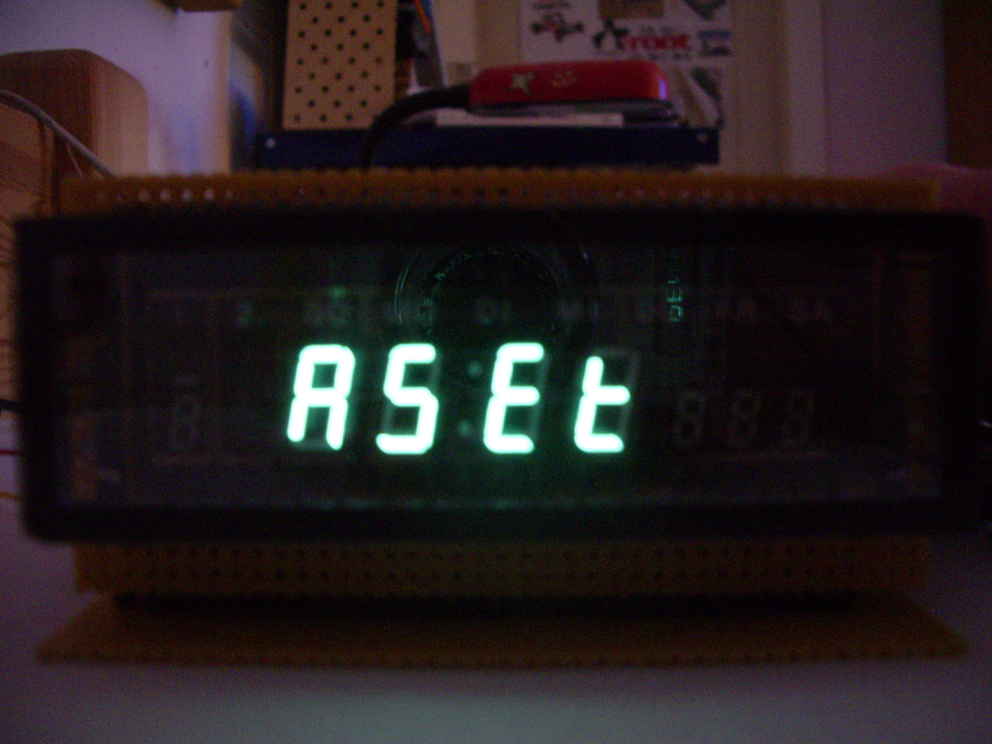
Menu 3
Alarm Set: Set alarm time
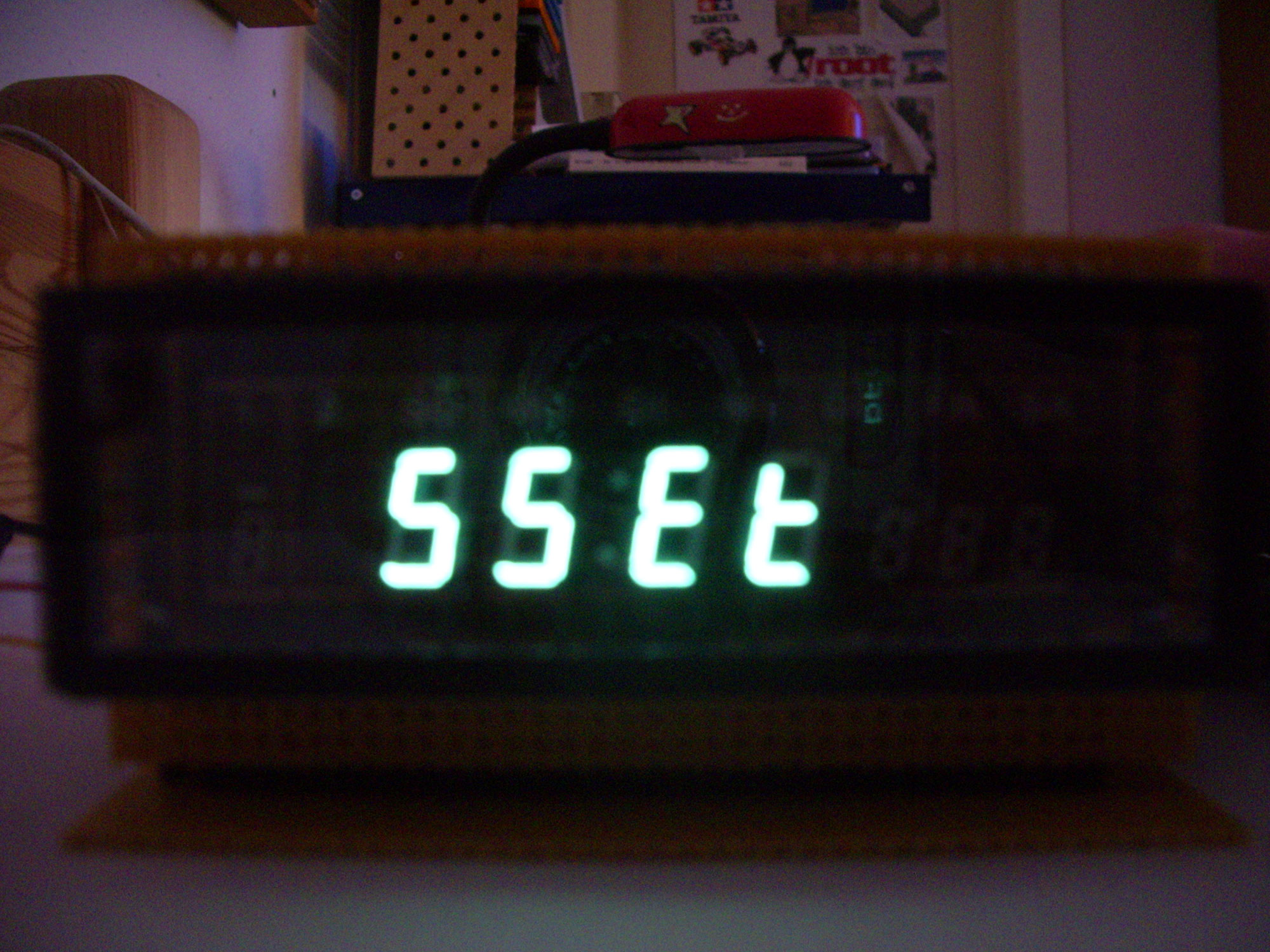
Menu 4
Sound Set: Select one of the 10 alarm sounds
Block diagram
Last but not least, I would like to show a schematic block diagram here, more detailed would be unnecessary due to the special VF display.
This alarm clock was used as a starting point for the development of the talking alarm clock 2 with IV-18 tube.