Solar MPPT charge controller with CN3722
Charge controller for LiIon or LiFePO4 batteries with maximum power point tracking and temperature monitoring
For quite a long time, I had the idea of charging the batteries of my IoT devices, such as the ESP8266 weather station in the garden, using a solar panel. This device has a relatively high power requirement due to the WLAN connection, as well as when it is not measuring and operating in deep sleep mode. The charge controller described below was developed so that the batteries no longer have to be recharged manually every few months.
It is suitable for charging one or more LiIon or LiFePO4 cells. The charging current and battery voltage are determined by resistors with the respective values. With a 5-10 Wp solar panel, the battery can be kept charged even in poor light conditions.
Solar cells reach their maximum output at a defined voltage. If this voltage drops, the charge controller reduces the charging current to keep the set input voltage constant. This ensures that the highest possible charging current is achieved in every light situation. This process is called Maximum Power Point Tracking. For standard 36-cell solar modules, for example, the maximum power point is around 16-18 volts.
Another important point is the temperature monitoring of the battery. Charging below 0 °C damages the cells irreparably, while storage and discharging are unproblematic. For this reason, an NTC temperature sensor is provided, which can either be soldered to the circuit board or connected externally via a connector and attached to the battery pack. At temperatures above 50 °C, the charging process is also interrupted for safety reasons.
Development
During the implementation of the project, I evaluated various charge controller ICs. In the end, I chose the CN3722 from Consonance because it is designed as an efficient step-down (buck) switching regulator and has both MPPT and temperature monitoring. The IC is also very inexpensive and ready-made circuit boards are already available from Aliexpress.
Theoretically, this would solve the problem except that these circuit boards are dimensioned for a significantly higher charging current. As the charging current decreases, the required inductance of the coil increases, and I was unable to find one in a suitable size. In addition, the boards had a fixed resistor soldered instead of the NTC, and there was only a single mounting hole. So I decided to design my own circuit board.
Circuit description
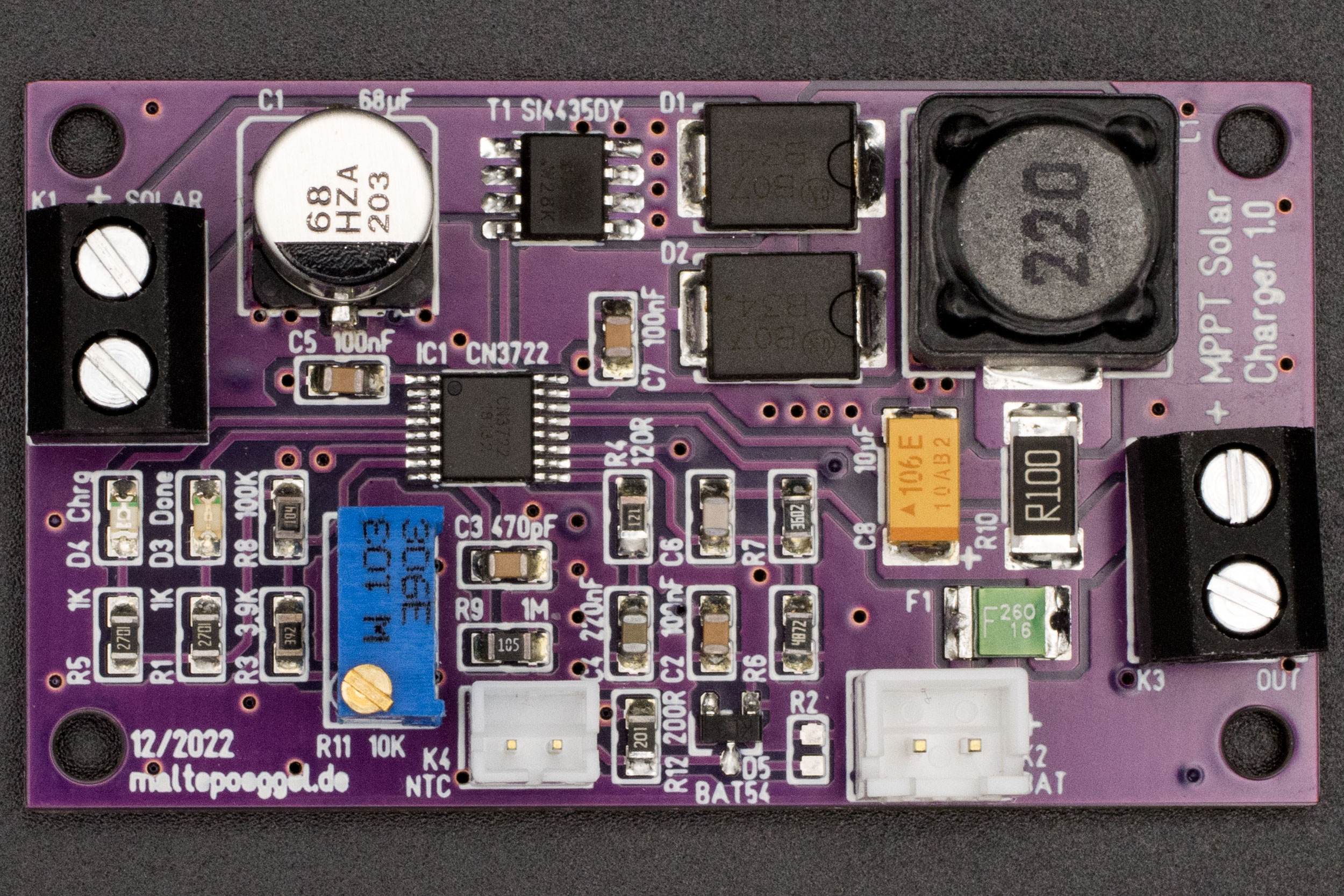
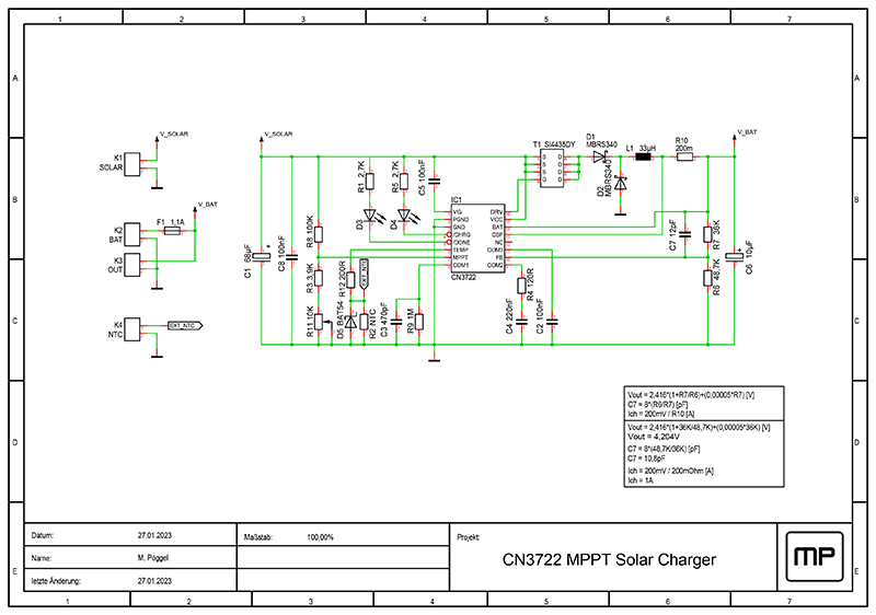
Where possible, the component identifiers correspond to those in the data sheet. The solar panel is connected to the screw terminal K1, the battery is connected to the JST XH socket K2 (grid dimension 2.5 mm) - please pay attention to the correct polarity. Only batteries with a protective circuit (BMS) should be used. The self-resetting fuse F1 is connected in between for additional short-circuit protection. The load is connected to terminal K3. Capacitors C1 and C8 stabilize the input voltage. The electrolytic capacitor C1 can be fitted either in SMD or wired (3.5 mm pitch). The voltage divider consisting of R3, R8 and the precision potentiometer R11 allows the MPPT voltage to be set in the range from 8.5 to 27 volts, thus covering the entire operating voltage range. If the NTC temperature sensor R2 (SMD, type 0603) is fitted on the circuit board, R12 is replaced by a 0 Ohm resistor and D5 is omitted. This also applies if no temperature sensor is to be used. R2 is then fitted with 10 kOhm. If an external temperature sensor is to be used, R2 is omitted and the external NTC is connected to the JST PH socket K4 (grid dimension 2.0 mm). Resistor R12 (200 Ohm) and diode D5 protect the input from overvoltage when the sensor is reconnected. The components C3 / R9, C4 / R4, C2 and C5 stabilize internal control loops and voltages of the charge controller. The field effect transistor T1, the diodes D1 and D2 and the coil L1 form a step-down switching regulator. R10 determines the maximum charging current. The voltage divider consisting of R6 and R7 determines the charging voltage. C7 stabilizes the voltage regulation. The charging status is indicated by LEDs D3 and D4. R1 and R5 are the associated series resistors. For input voltages above 21 volts, their values should be increased slightly if necessary in order not to exceed the allowed power loss. The tantalum capacitor C6 stabilizes the output voltage of the switching regulator.
Dimensioning of the components
The values of R6, R7, C7, R10 and L1 are determined by the parameters of the solar panel and battery. In this example, they are designed for a 1S LiIon battery (4.2V) and 1A charging current. The calculation is based on the data sheet and the example circuit.
The resistors R6 and R7 determine the end-of-charge voltage. For lithium batteries, this must be maintained with an accuracy of +-50mV. As the reference voltage of the charge controller also has a minimal temperature drift, it is advisable to select the voltage as precisely as possible or slightly below it. Resistors with a tolerance of 1% are required. To simplify the calculation (data sheet page 6), I have created a LibreOffice Calc document. I have also generated a table containing all combinations of E24 and E48 series resistors suitable for different battery types. This can be downloaded at the bottom of the website.
As the voltage divider remains permanently connected to the battery, the quiescent current must also be kept in mind. A particularly high-impedance voltage divider means lower current consumption, but is easier to affect. I have therefore used the existing divider with about 50µA as a reference. The capacitor C7 is then calculated based on the two resistance values.
| Battery type | Voltage should (is) | Resistor R6 | Resistor R7 | Capacitor C7 | |
|---|---|---|---|---|---|
| LiIon 1S | 4,2V | (4,204V) | 48,7kΩ | 36kΩ | 12pF |
| LiIon 2S | 8,4V | (8,375V) | 48,7kΩ | 120kΩ | 3,3pF |
| LiIon 3S | 12,6V | (12,596V) | 48,7kΩ | 205kΩ | 2,2pF |
| LiFePO4 1S | 3,6V | (3,593V) | 48,7kΩ | 23,7kΩ | 18pF |
| LiFePO4 2S | 7,2V | (7,197V) | 82kΩ | 162kΩ | 4,7pF |
| LiFePO4 3S | 10,8V | (10,809V) | 48,7kΩ | 169kΩ | 3,3pF |
The charging current (data sheet page 7) is determined by R10. It is important to remember to adjust the self-resetting fuse F1 if necessary. The saturation current of coil L1 should also be dimensioned sufficiently (approx. factor 1.5-2) above the charging current.
| Charging current | Resistor R10 |
|---|---|
| 1A | 200mΩ |
| 1,5A | 130mΩ |
| 2A | 100mΩ |
| 2,5A | 82mΩ |
| 3A | 68mΩ |
As already mentioned, the inductance of the coil depends on the charging current and input voltage, whereby a lower current generally requires a higher inductance. The table (excerpt from page 9) shows the necessary values, here in the range of 1-3 amperes, limited by the diodes used.
| Charging current | Input voltage | Inductance L1 |
|---|---|---|
| 1A | > 20V | 40µH |
| < 20V | 30µH | |
| 2A | > 20V | 30µH |
| < 20V | 20µH | |
| 3A | > 20V | 20µH |
| < 20V | 15µH |
Either an NCP18XH103F03RB placed directly on the circuit board or an external MF52 (10kΩ) can be used as an NTC temperature sensor. The resistance of 10kΩ is specified at an ambient temperature of 25 °C. The latter sensor is available with different B values. This is a material constant, specified in Kelvin, which defines the characteristics of the NTC. If we compare the MF52 sensors with different B25/85 values as the temperature falls, the resistance value rises faster for the variant with a higher B constant and thus leads to an earlier cut-off.
| tempLow (≈28kΩ) | tempHigh (≈3,2kΩ) | |
|---|---|---|
| MF52B (3435K) | < 0 °C | > 57 °C |
| MF52B (3950K) | < 3 °C | > 52 °C |
The NCP18XH103F03RB has a B25/85 constant of 3434K and is therefore comparable to the MF52B (3435K). If you want to be on the safe side and want to interrupt the charging process already shortly before 0 °C, use the MF52B (3950K). Ready-made NTCs with cable are available on Aliexpress. These can be attached directly to the battery with some Kapton tape or even heat shrinked into the battery pack.
Charging method
The charging process begins as soon as the MPPT voltage is reached. For this purpose, the charge controller uses a CCCV method commonly used for lithium batteries, in which charging takes place at constant current until the end-of-charge voltage is reached and then continues at constant voltage. If the charging current drops low enough, the charging process is terminated. If the battery voltage falls below a defined threshold, the charging process is resumed. In addition, deeply discharged batteries are pre-charged with a low current.
Two status LEDs indicate the charge status if voltage is present from the solar panel. The red LED lights up if the final charging voltage has not yet been reached. This is independent of whether charging is in progress or not (e.g. because MPPT voltage not reached or invalid temperature range). A fully charged battery is signaled by the green LED.
Adjusting the MPPT voltage
For calibration, the whole setup without battery is connected to a laboratory power supply and the voltage at the input is set to the desired MPPT voltage. The precision trimmer R11 is now adjusted until the point between the permanent illumination of the red LED and the rapid flickering of both LEDs is found.
If there is no data sheet for the solar panel used, the appropriate MPPT voltage can be determined by a series of measurements. To do this, the panel is optimally aligned in strong sunshine and several measurement points of current and voltage are recorded with an electronic load in constant current mode. This allows the power to be calculated for each point and the voltage to be selected for the best performance.
Links
- Circuit board at Aisler
- Circuit board OSH Park
- Website of the charge controller manufacturer
- Datasheet CN3722
- Example circuit CN3722
Downloads
Related projects
License
The PCB layout I created may be used freely for private use, but the author's name must remain on it (CC BY-NC-SA). The schematic is not subject to any restrictions.