TFT2PC
Using LVDS and TTL TFT displays as PC monitors
A frequently asked question in modding and hobbyist forums is if and how TFT displays can be connected to a normal PC with little effort. This page should go into more detail and describe how and why which panels can be connected.
TFT displays, formerly only used in notebooks and today already standard in PCs and consumer electronics, have become a mass product. Cheap panels can easily be scrapped - much too good to dispose of! Of course, the pinout is as different as the application. Almost every display has a special connector and a different pinout. This must be discovered first. Each manufacturer provides data sheets, these can be easily found under their type designation using well-known search engines.
Determining the signal type
Depending on the application and age, the necessary signal type differs. With old black and white LCDs, the display content was transmitted in two halves, with color TFTs, the TTL or LVDS standard is usually used. Small displays, like they are used in portable TVs, DVD players or entertainment devices mostly use a composite or RGB video signal. I would now like to briefly discuss all signals known to me:
TTL Displays are mainly used in older notebooks (ca 1995 to 2004). They need a digital, parallel RGB + Sync video signal with a voltage of 3.3 or 5 volts. You can recognize them by connectors like HSync, VSync, Red MSB ... Red LSB and so on. If you can do without a larger color depth, you can use them with 4 bit color depth (16 colors) with little effort on the Vesa Feature Connector, which is available on many older graphics cards. Also some older industrial PCs (PC104) offer a TFT controller for such displays. Here the timing must be exactly right; each panel can have different values. Mostly different models can be selected in the BIOS.
LVDS Displays are almost common nowadays. They process a digital differential signal and can be easily identified by the DATA0+ DATA0-,... lines. Again, older models may still work with 5 volts operating voltage, new ones only with 3.3. The digital pixel data as well as the synchronization are transmitted serially here. Mostly 3 of such double lines are available. In a few cases also 6 (DUAL-LVDS). You can hardly build your own control electronics, but you can find suitable converter boards in TFT displays or as universal converters on eBay. More about this later.
Dual Scan Displays are the predecessor of TTL displays. Here the display is physically divided into two halves, which are transmitted at the same time. If you want to connect them to the VESA connector, the screen content has to be buffered. There are more complicated solutions with microcontrollers or CPLDs, but the effort is hardly worth it anyway due to poor resolution.
Composite video or RGB displays are often used in small TVs (5 to 7 inch) or video game accessories (e.g. PSone TFT, PS2 TFT). Composite video displays can be easily connected to the TV out of the graphics card, RGB displays only with a Scart RGB signal (Satellite receiver etc.) where a sync signal must be generated.
Backlight
Mostly cold cathode tubes (CCFL) are used. These need an ignition voltage of about 2kV (2000V) and a constant current (the voltage reduces to 600-700 Volt during operation). CCFL's should in any case only be operated with a suitable inverter. Either you make the appropriate inverter work, or you use one from the casemodding area. The lengths of the tubes should be the same so that the luminous flux fits and the tube does not overheat.
Inverters can have different control systems. Ranging from a simple on-off signal over a brightness voltage to control via I2C or other bus systems. In any case you should have a look at the datasheet of the controller IC, if there is no datasheet you can analyze the connections with an oscilloscope.
Application and controlling
Now that the pinout and inverter are known, you should be clear about the intended use. A TTL panel can be used with a maximum of 16 colors at the Vesa connector, so it is best used as a console monitor for a Linux server, but totally unsuitable for desktop use. If an industrial PC is available, the LCD controller can be used to control the display with higher color depth.
The highest color depth can be achieved with LVDS panels. The problem is that suitable converters are hard to find. These boards contain a complete control and signal processing, and of course an on screen display. It might work to use such converters from a defective TFT display. Whether the data signals fit can differ from case to case. You can be quite sure with a universal converter, as they were offered on eBay for some time. In the meantime, these boards are unfortunately no longer available.
Also newer industrial PCs may have a LVDS TFT connector. By the way, LVDS is not to be confused with DVI - these are two completely different standards. Similar to VGA, a converter board is needed here, too!
A cheap alternative is the PSone TFT, an accessory for the Sony Playstation. There is a panel built in which can directly process a composite video signal! This can be connected directly to the TV Out of the graphics card, or other signal sources. A disadvantage is that the resolution is limited to 520x324 (standard TV resolution). But since the displays are quite small anyway, larger fonts can be read without problems.
Connecting a TFT display via LVDS with converter board
The common interface of TFT panels today is called LVDS. In the past, external electromagnetic influences such as sparks or changing magnetic fields could massively interfere with data transmission. With increasing resolutions and repetition rates, a new standard was needed: LVDS, which stands for Low Voltage Differential Signal and is, as the name suggests, a differential data transmission. Roughly speaking, this bus consists of three conductors, namely ground as well as Data+ and Data-. The inverse of D+ is always transmitted on D-. If a field is scattered from outside, the voltages on both data lines are increased simultaneously, but the difference always remains the same and is ignored by the receiver. Fast data rates can now be transmitted more easily.
Let's first take a look at the pinout of the 30-pin LVDS connector commonly used in laptop displays:
| Pin | Signal | Description |
|---|---|---|
| 1 | GND | Ground |
| 2 | VCC | Voltage Panel 3,3V |
| 3 | VCC | Voltage Panel 3,3V |
| 4 | V EEDID | Voltage ID Chip 3,3V |
| 5 | TEST | not connected |
| 6 | CLK EEDID | Clock ID Chip |
| 7 | DATA EEDID | Data ID Chip |
| 8 | D0- | LVDS Data 0 (neg) |
| 9 | D0+ | LVDS Data 0 (pos) |
| 10 | GND | Ground |
| 11 | D1- | LVDS Data 1 (neg) |
| 12 | D1+ | LVDS Data 1 (pos) |
| 13 | GND | Ground |
| 14 | D2- | LVDS Data 2 (neg) |
| 15 | D2+ | LVDS Data 2 (pos) |
| Pin | Signal | Description |
|---|---|---|
| 16 | GND | Ground |
| 17 | CLK- | LVDS Clock (neg) |
| 18 | CLK+ | LVDS Clock (pos) |
| 19 | GND | Ground |
| 20 | NC | not connected |
| 21 | NC | not connected |
| 22 | NC | not connected |
| 23 | NC | not connected |
| 24 | NC | not connected |
| 25 | NC | not connected |
| 26 | NC | not connected |
| 27 | NC | not connected |
| 28 | NC | not connected |
| 29 | NC | not connected |
| 30 | NC | not connected |
It is noticeable that apart from the data lines and the supply voltage, some pins are marked with EEDID. This is a VESA standard to store identification data and manufacturer-specific timing values in the display. A corresponding EEPROM is located on the board. The notebook bios can read these values and initialize the graphics chip accordingly. In addition, the notebook manufacturer can install displays from different manufacturers in the same notebook series without changing the BIOS during production.
The image data is sent serially, and there are also four (single link) or eight (dual link) wire pairs for image data and clock signal (clock- clock+). The color bits as well as sync signals are distributed on them. The data stream looks like this:
To generate such a data stream from a VGA or DVI signal, there are suitable converter boards. These boards contain the same chipsets that are used in TFT monitors. Universal converters sometimes even come with configuration software, others have jumpers. If no suitable connection cable for the TFT to be used is included, the wires must be researched and connected according to the pin assignment and data sheet of the display.
Possible suppliers:
TTL TFT Display on Vesa Feature Connector
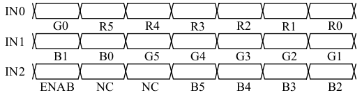
A simple solution is to connect the panel to the Vesa Feature Connector. However, this is only available on older ISA and PCI graphics cards (e.g. from Pentium 1 times). The characteristic of suitable displays is the parallel transmission of the color signals, therefore per color signals like R0, R1, R2 and so on are visible in the datasheet. Displays with 5V TTL interface can be connected directly, but usually only 16 colors are possible. Thus the display can be used at most as a terminal for a Linux server.
Instructions and information:
- Instructions: Connecting a TFT display (Sharp LQ9D01C) to the VESA Connector
- LCD project by Artur Samborski: Podlaczamy LCD z laptopa do PC (polish)
- Tutorial: Uses the VGA port and Schmitt trigger: area26 - VGA-LCD (PDF Mirror)
- Datasheet Sharp LQ9D011
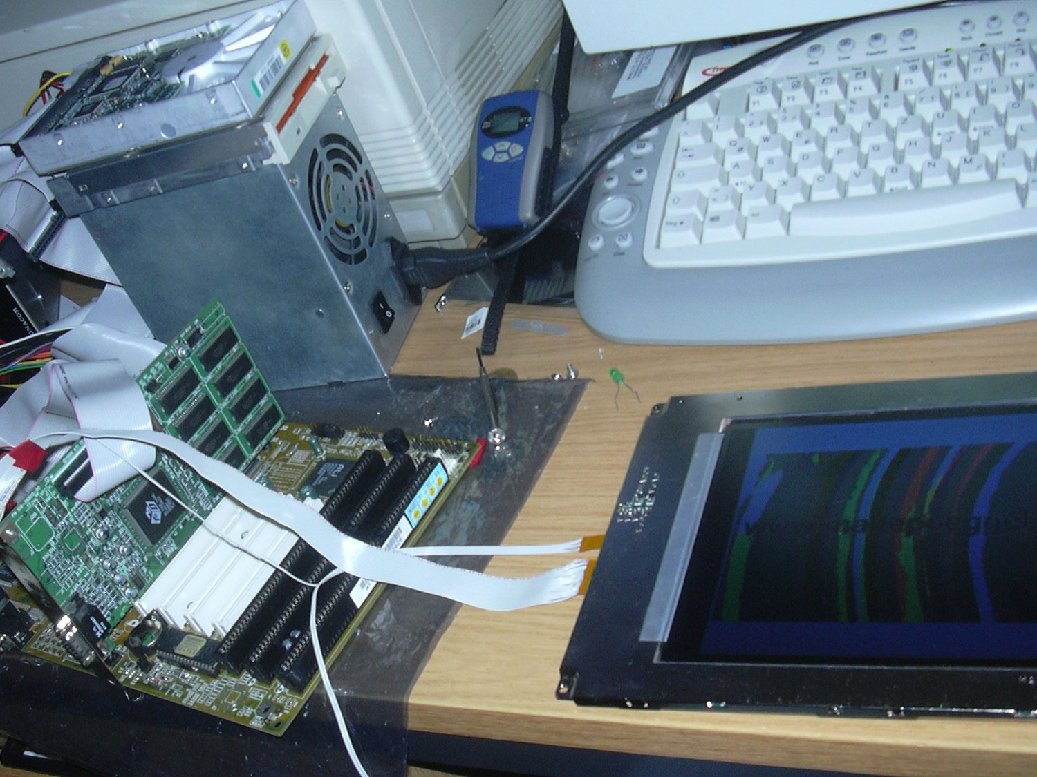
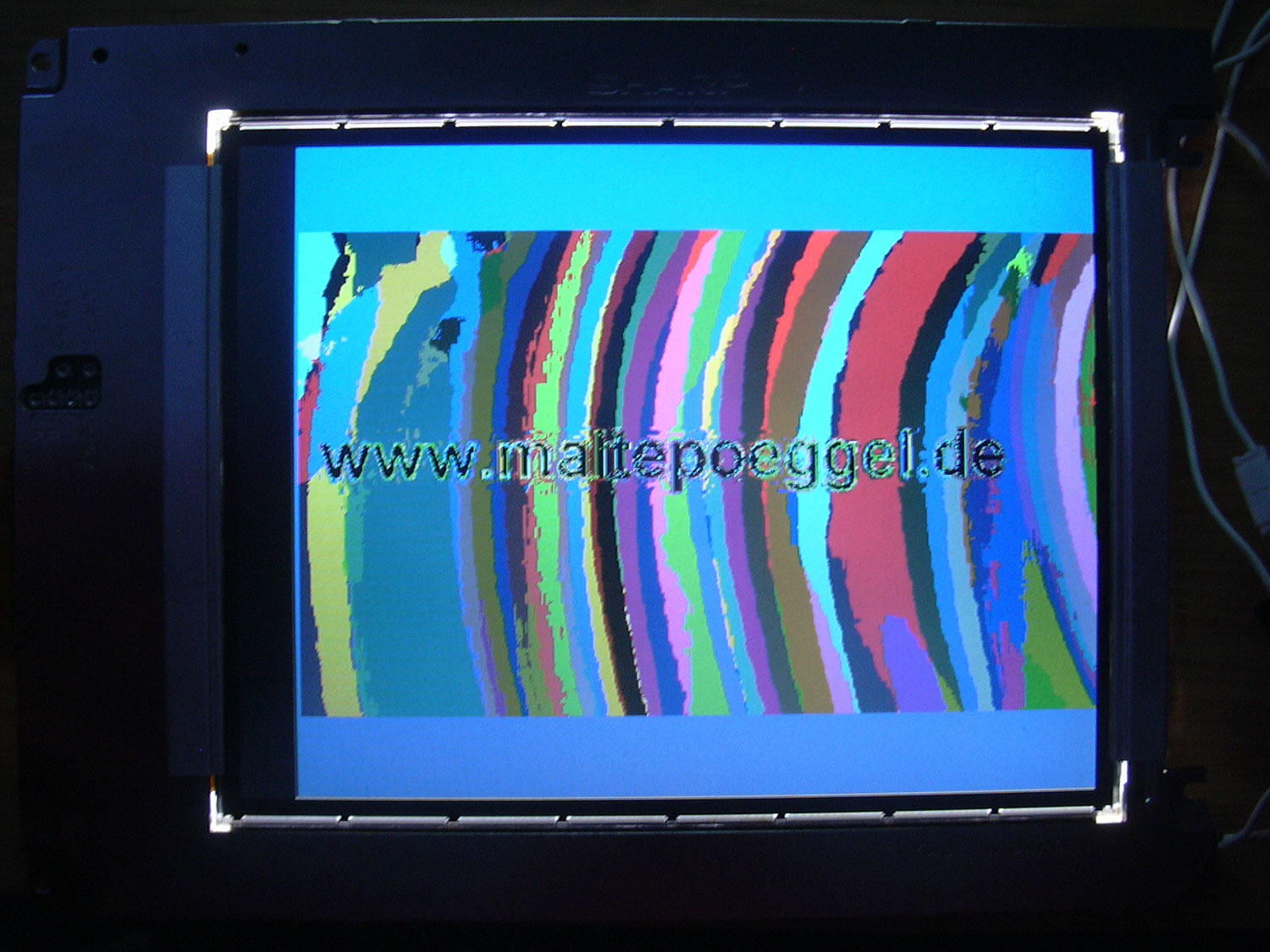
If the image is slightly shifted as seen above, it may help to get the clock signal from a separate oscillator instead of the graphics card. More information can be found in Arthur's manual.
TTL TFT on industrial PC (PC104)
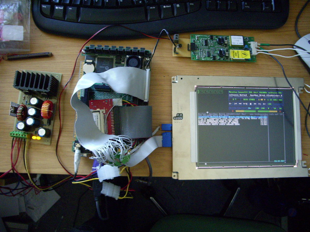
Some industrial PCs have special graphic cards that can drive TFTs. For this the necessary connections are led out on a connector. Mostly the choice of suitable displays is limited to a few types. These are selected in the BIOS. With a little luck, the pinout can be found in the manual of the PC104. As you can see in the picture, I simply made the matching adapter myself.
Composite Video TFT on the PC
Displays that have a video input can be used with old graphics cards with TV out. As mentioned above, the resolution is very limited. Michael (Deepnight) has written a small tutorial about this: