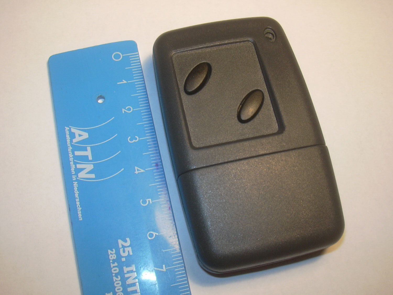
TV-B-Gone
A remote control that turns off any TV
The TV-B-Gone is a remote control that can turn off almost any TV. There are over 50 remote control codes stored in an Atmel Tiny85 microcontroller, which the original remote control of the manufacturer would send.
There is also an open source publication with schematics and program code available on the net. (Link below) However, the layout was still too big for me, and to have some fun without being discovered, I created a very small version with an integrated key light.
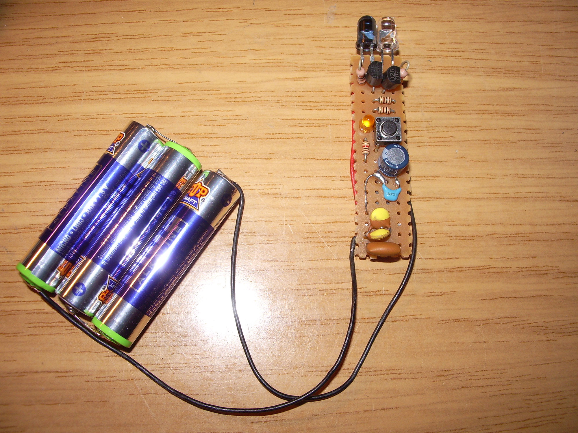
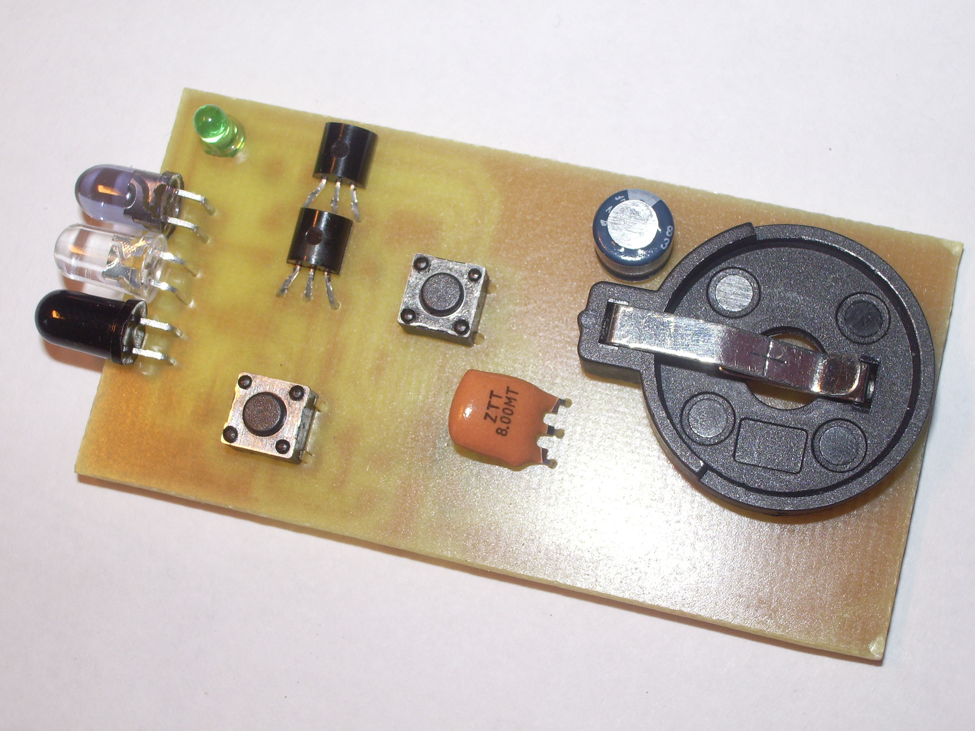
To get familiar with the hardware, I built the circuit on a breadboard. Some components I got from my former internship company in the form of scrap remote control parts, and I found the remaining parts in my tinkering box.
Demonstration video with Philips 100Hz CRT TV
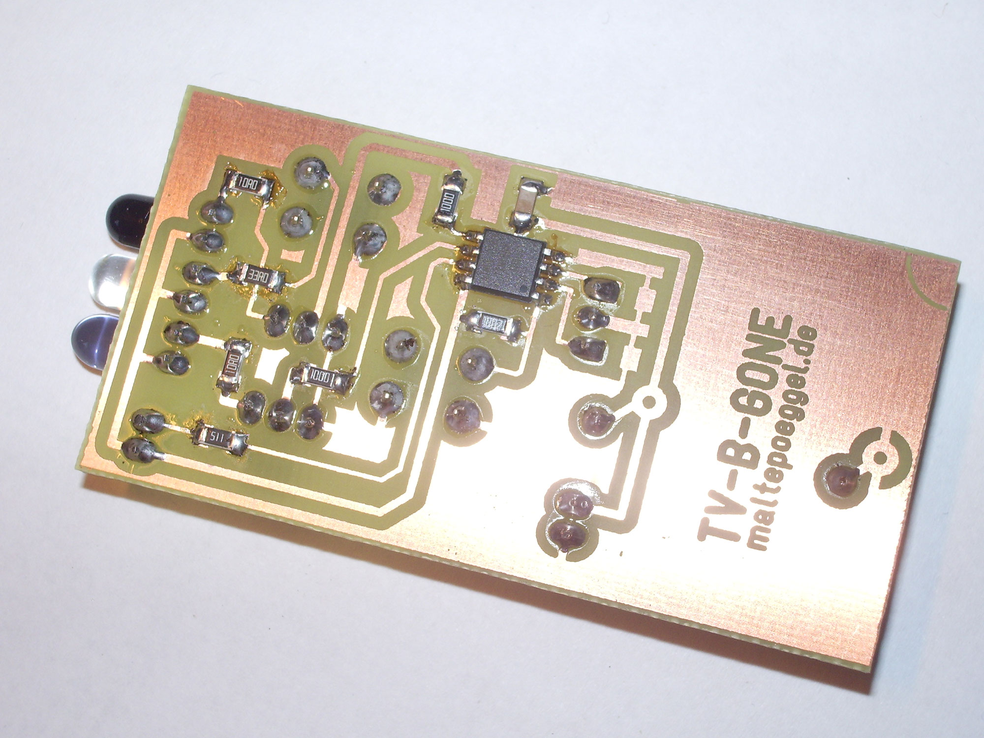
All tests at the electronics shop around the corner were successful. And so it was time for the layout design:
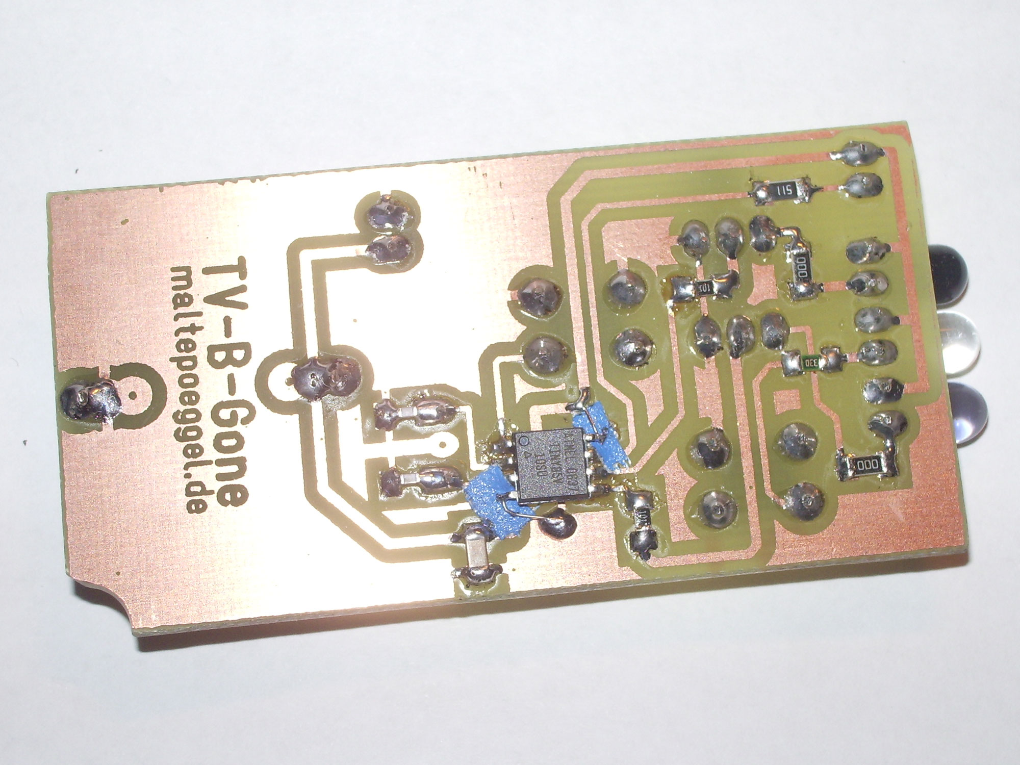
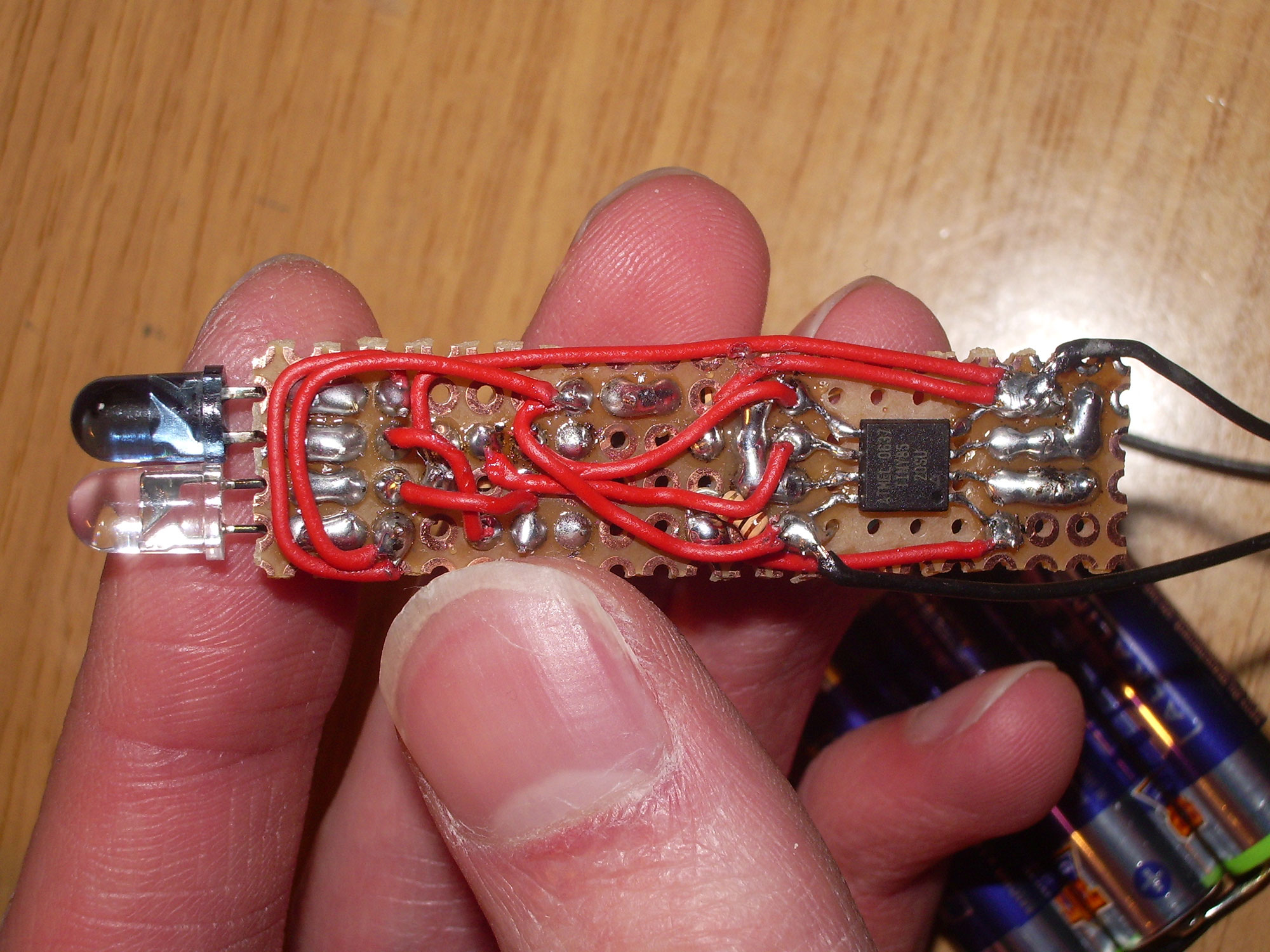
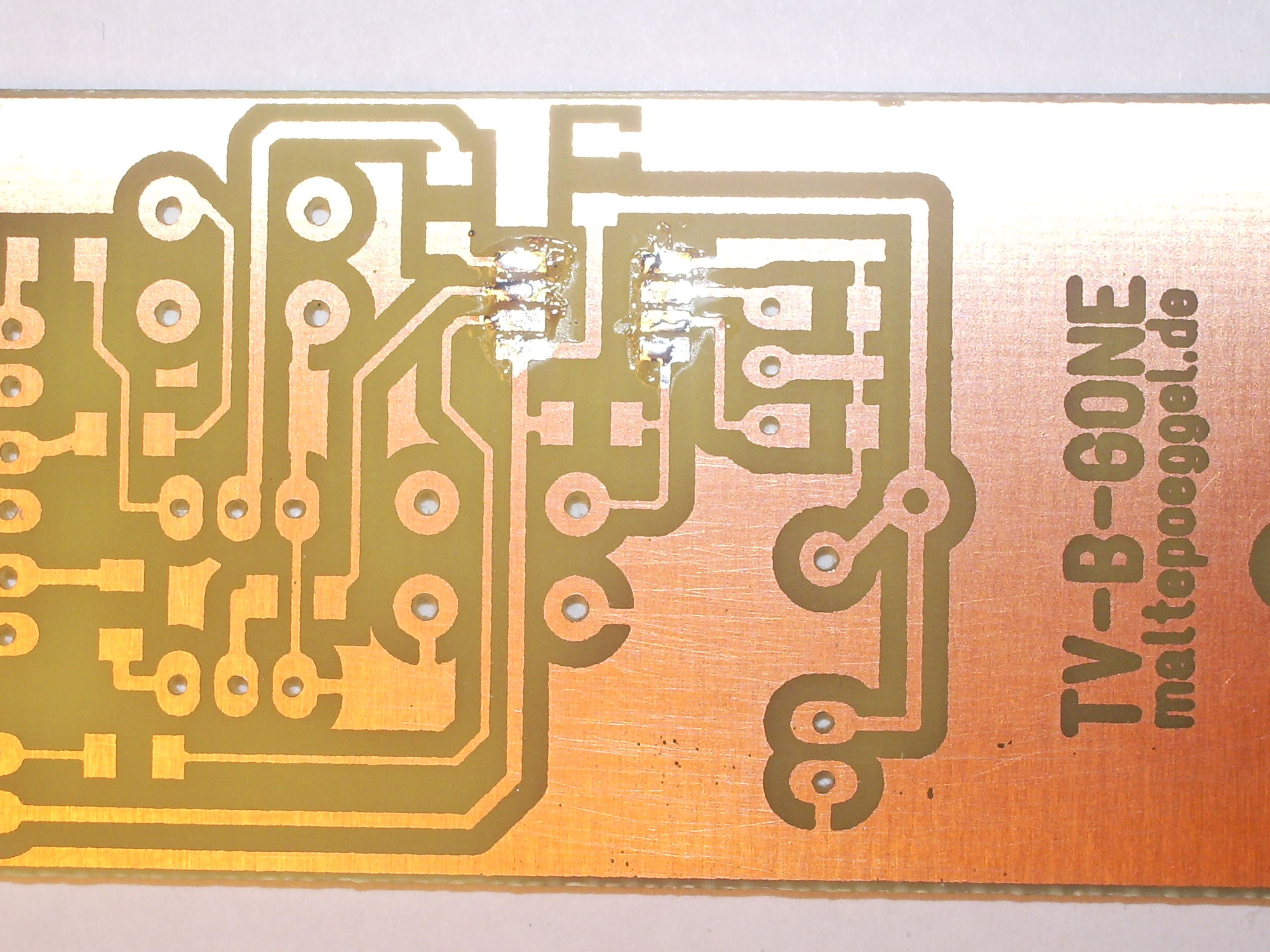
In the first board a small error happened at the operating voltage pins of the microcontroller. I was able to fix it with some insulating tape and some wire.
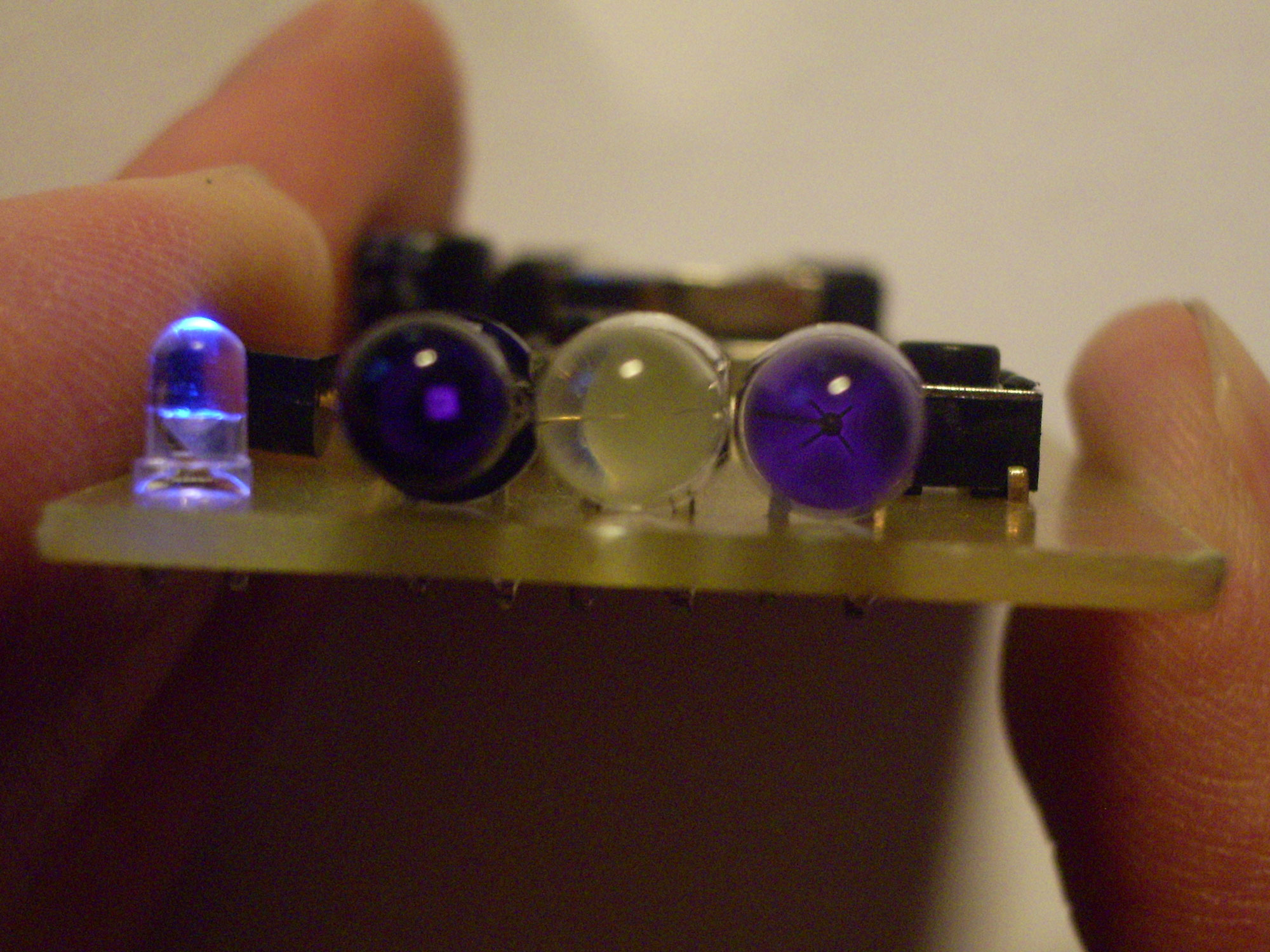
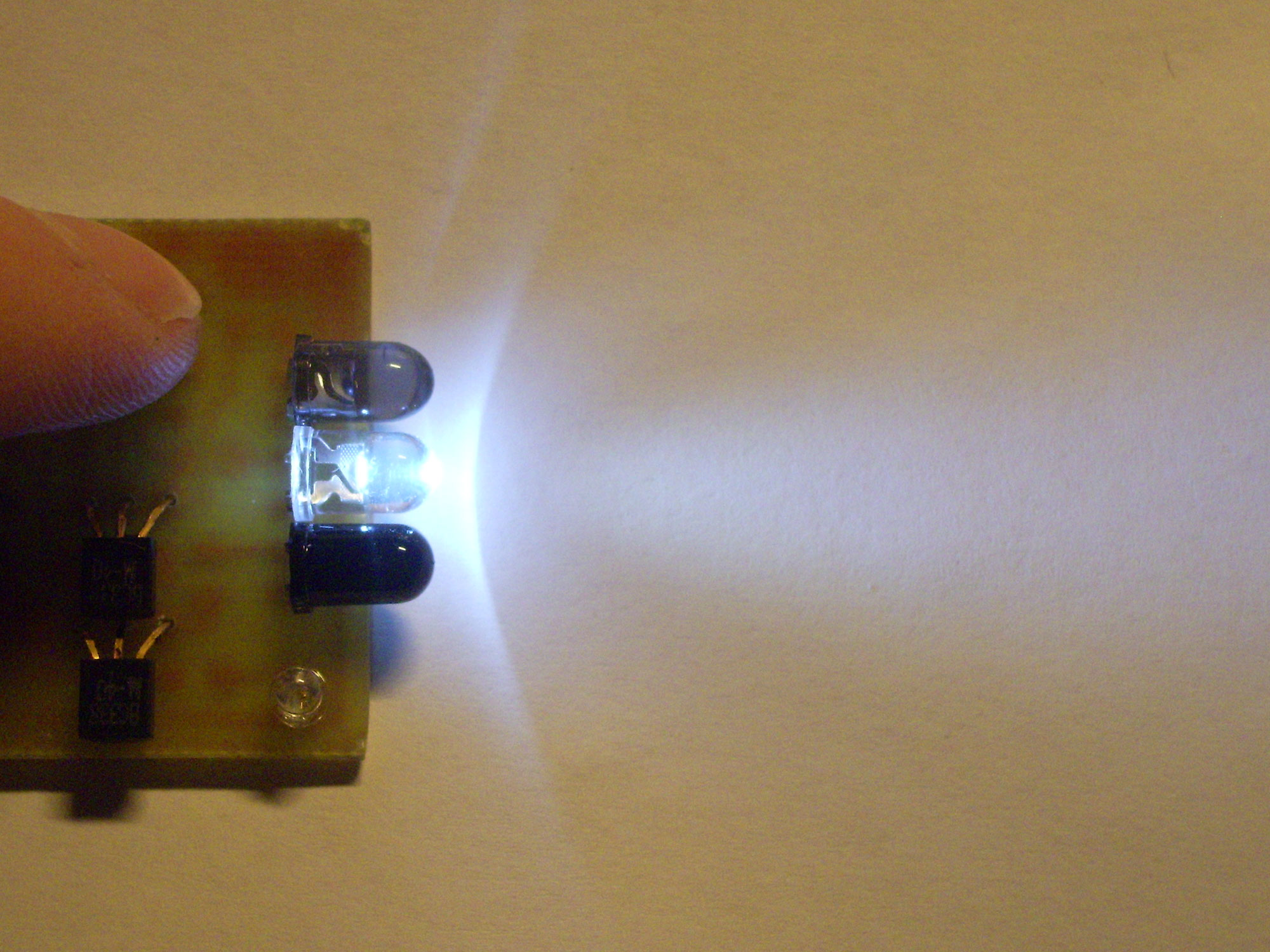
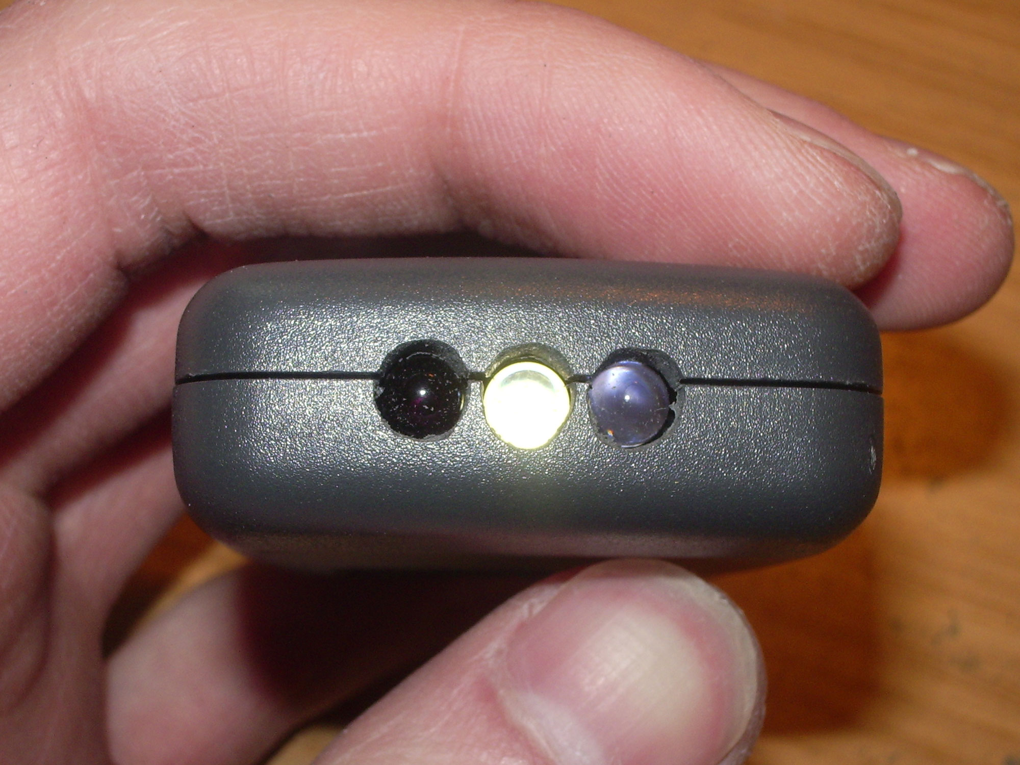
Infrared LEDs and key light function in operation.
Video of the creation of the board, as well as tests
Kit
When I introduced the project in Paul's forum, I quickly found some people who were interested. Since I had put together a few kits, I would like to explain the assembly in more detail in the following.
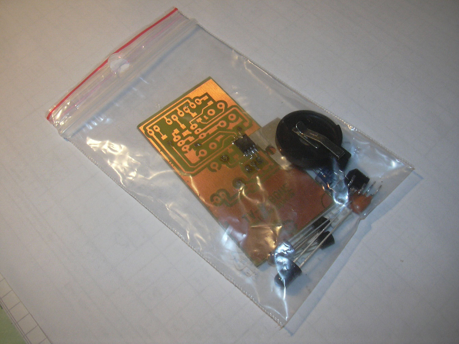
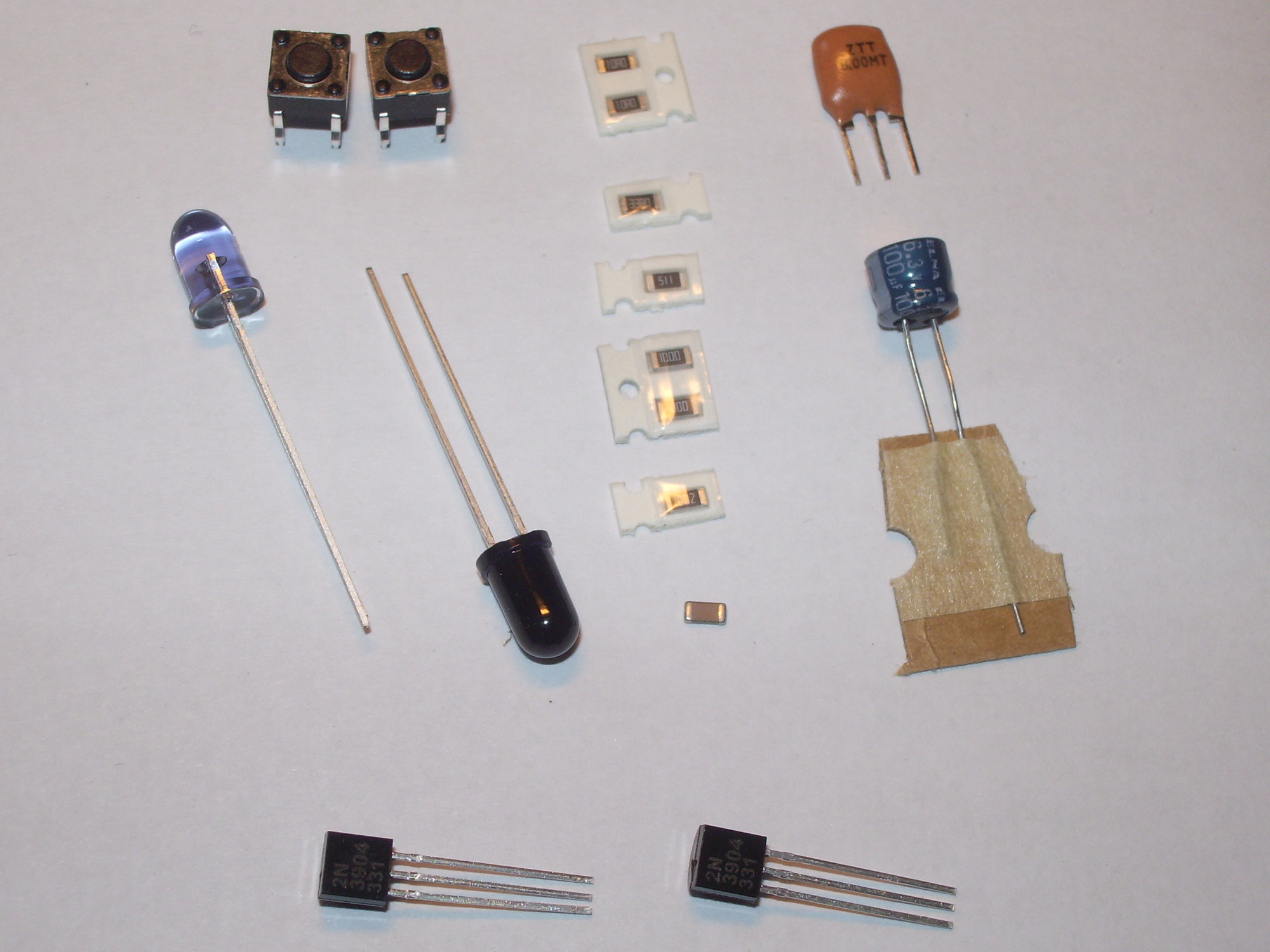
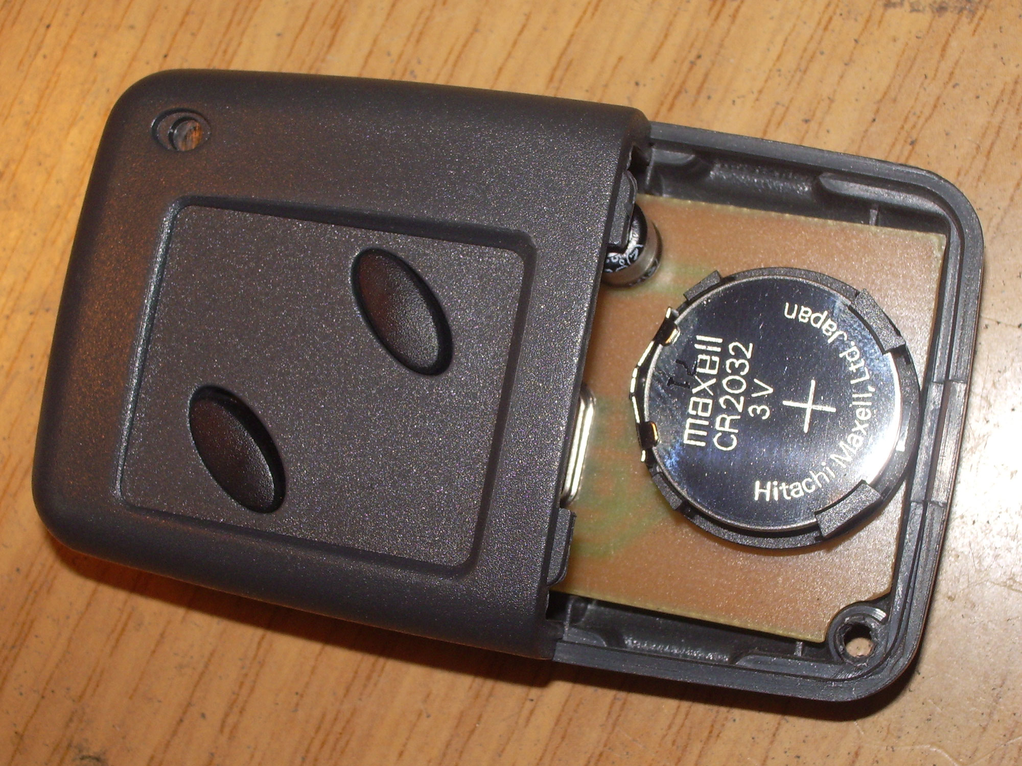
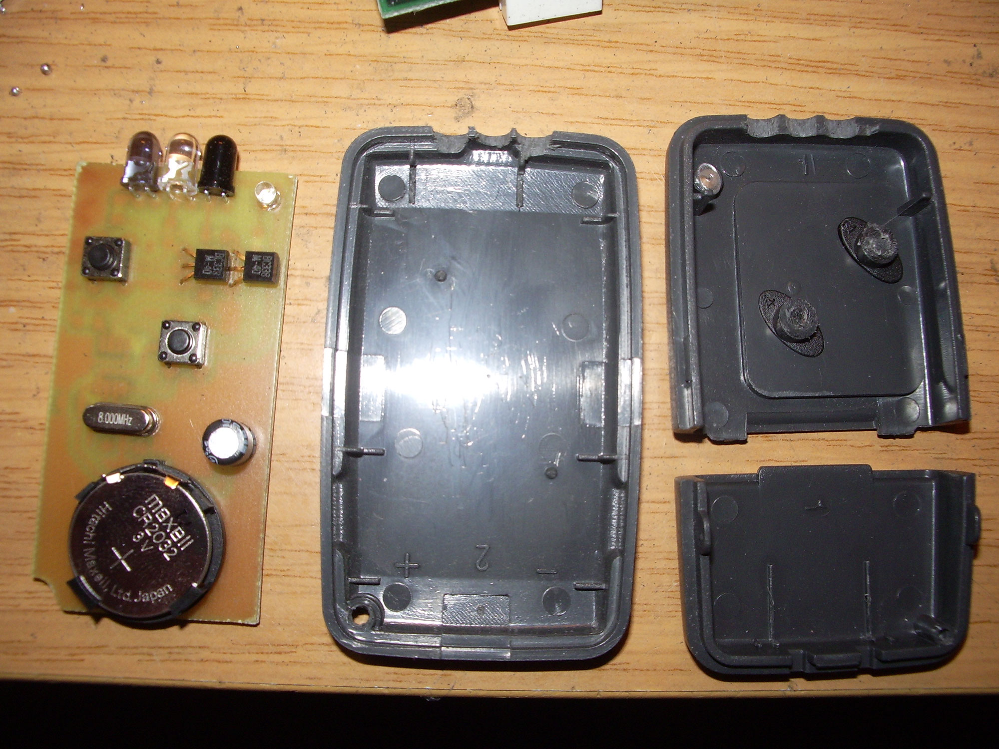
The following components are included: SMD resistors 1206: 10 Ohm (2x), 100 Ohm (2x), 33 Ohm, 1K, 10K. Transistor 2N3904 (2x), SMD capacitor 1206: 100nF. Electrolytic capacitor 100µF, Tiny85 microcontroller, infrared diodes: LD274-3, SFH 415, 8MHz ceramic resonator, micro pushbutton, circuit board, battery holder, CR2032 button cell, case. If desired, a 5mm LED (super bright white or blue) is needed for the key light function and any 3mm LED for the status display. These are not included.
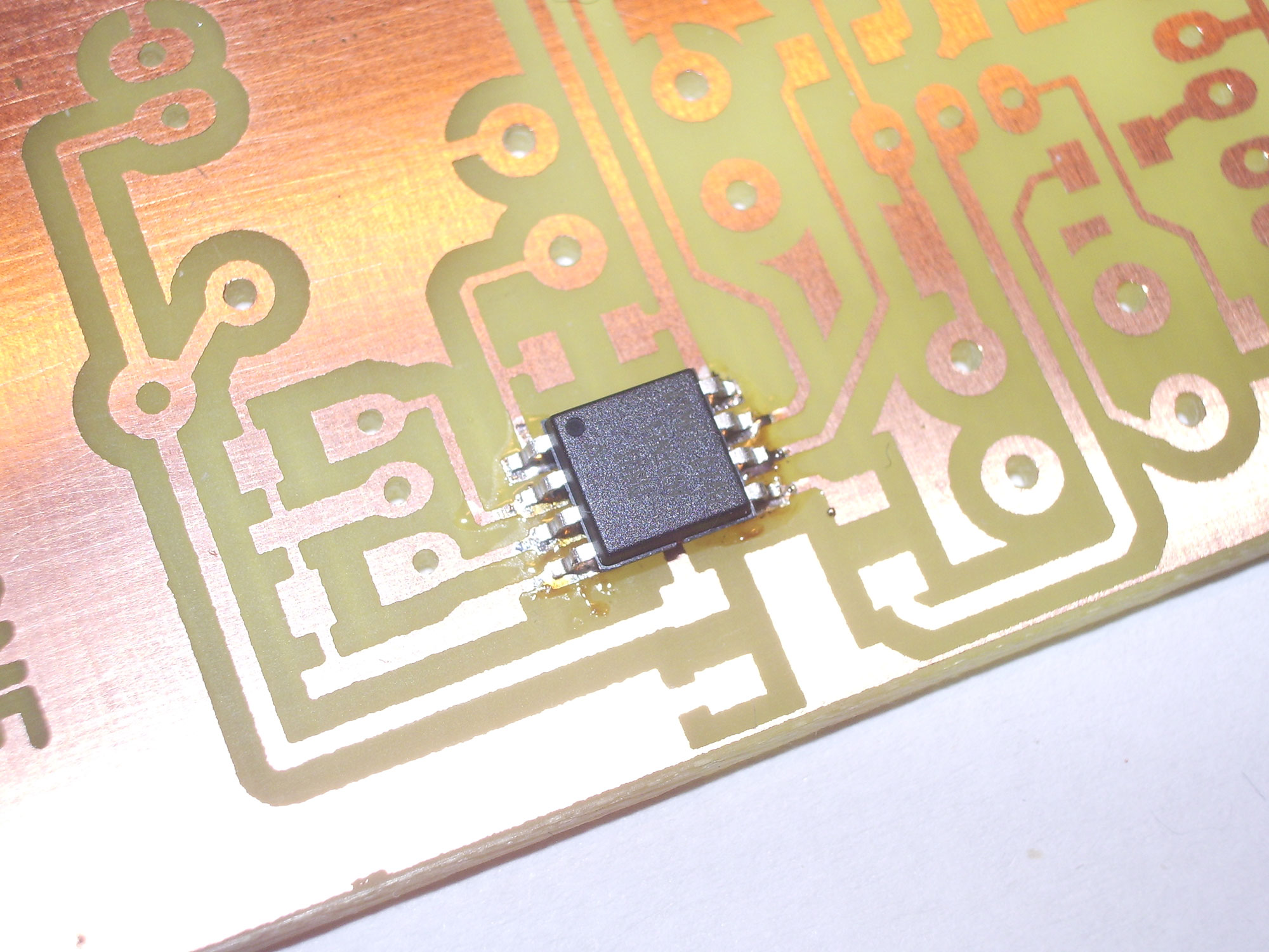
The soldering pads for the microcontroller are first tinned and cleaned again with solder wick. The controller is positioned and heated at two pins. If it sits correctly all connections are soldered properly.
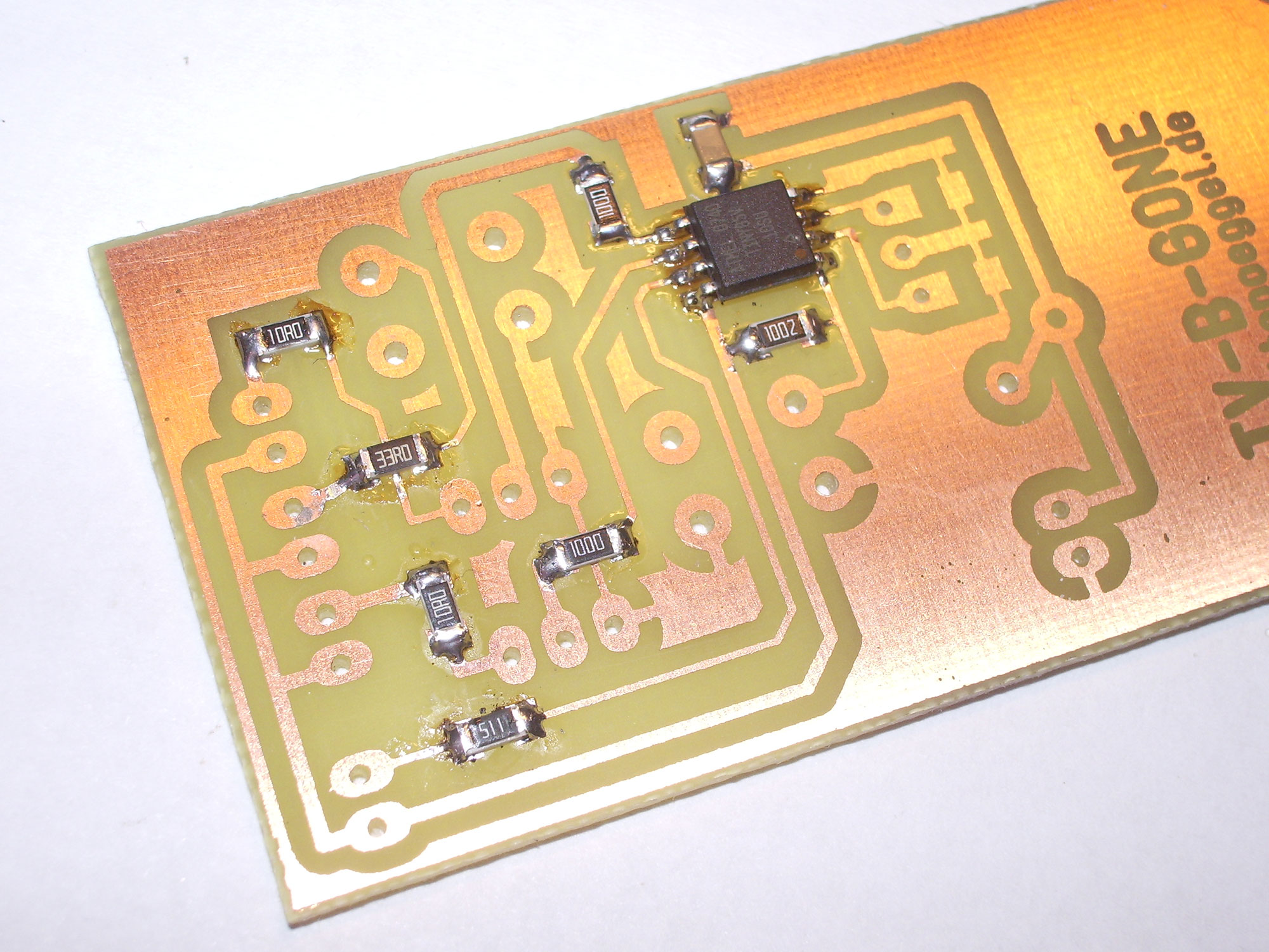
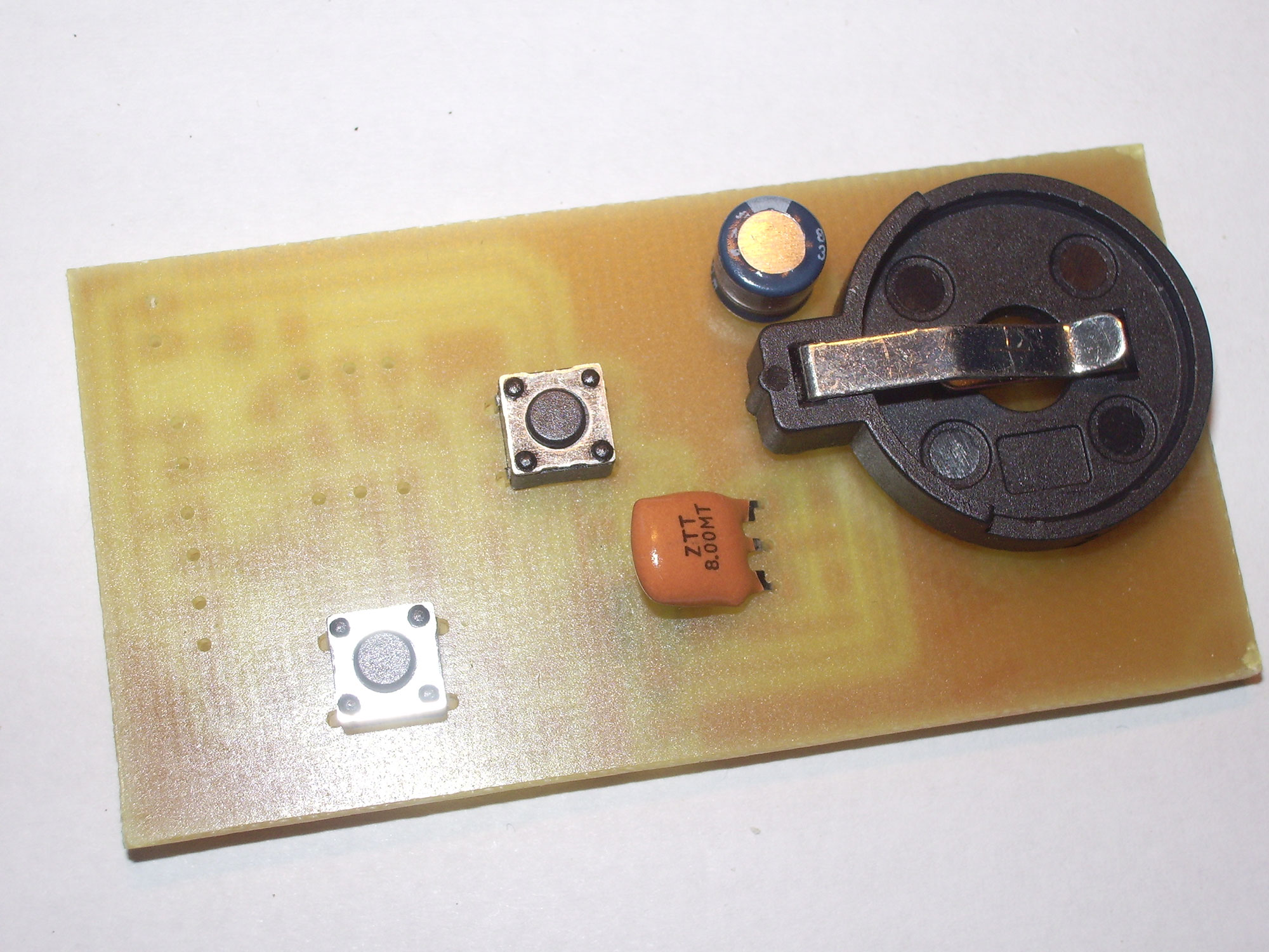
Next, all remaining SMD components are soldered, afterwards buttons, capacitor, battery holder, ceramic resonator (alternatively quartz and 2x22pF).
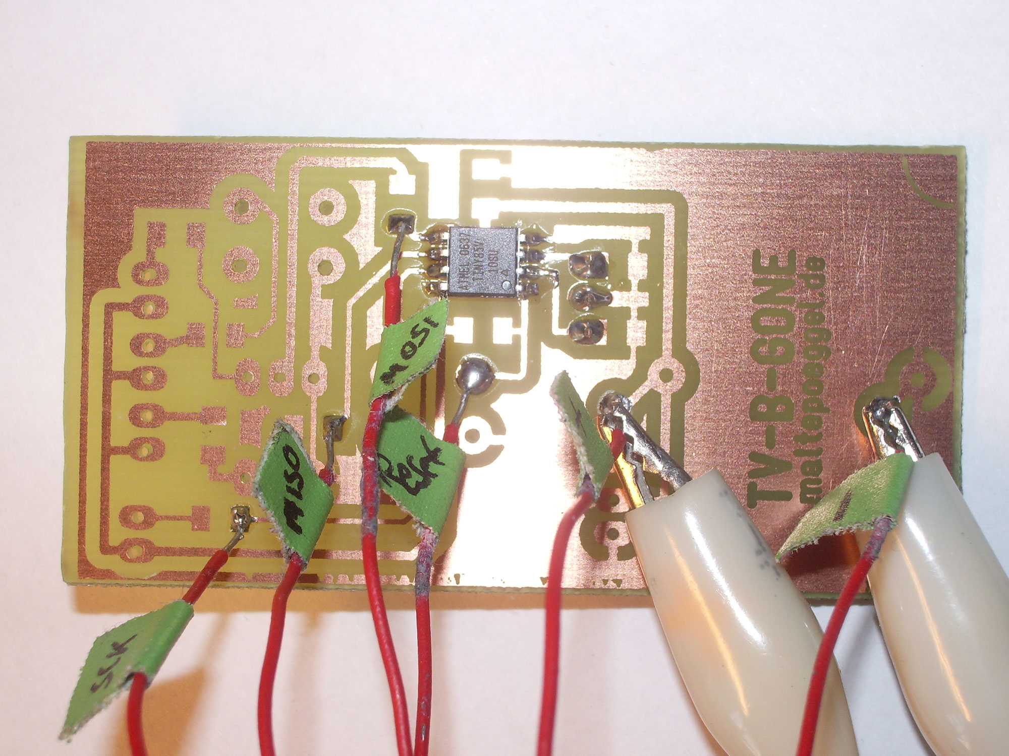
Now the Atmel microcontroller needs its software. Wires from the ATMEL ISP programming adapter are soldered to the appropriate points. Also a 5V voltage is applied to the pins of the battery holder.
Using Ponyprog the lock & fuse bits are set and the program is flashed into the controller.
The most important pins are shown here:
That' s how the lock & fusebits have to be set.
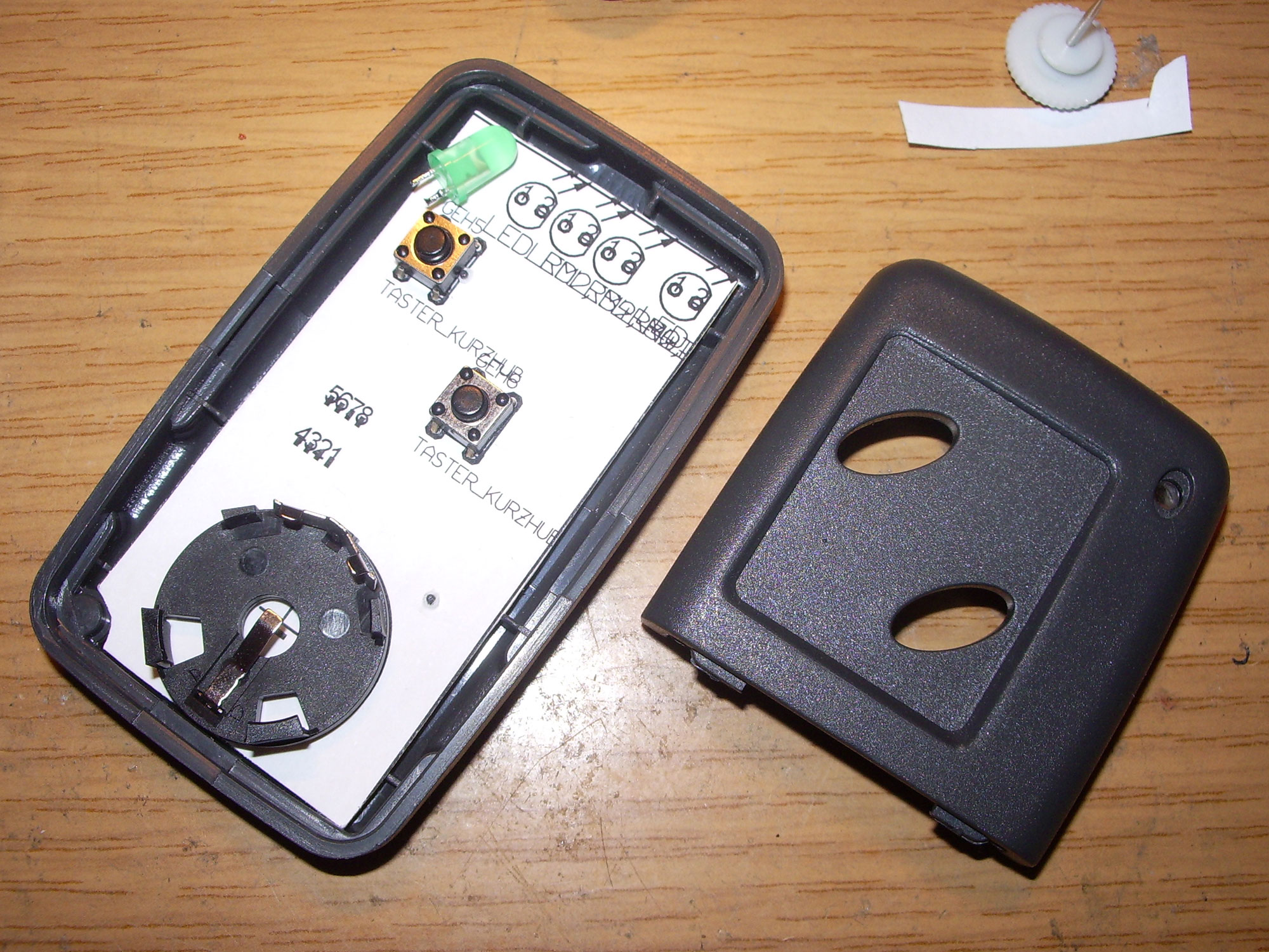
Finally all other components are assembled. Attention: Let the LEDs stick out a little bit more so that they look out of the case afterwards.

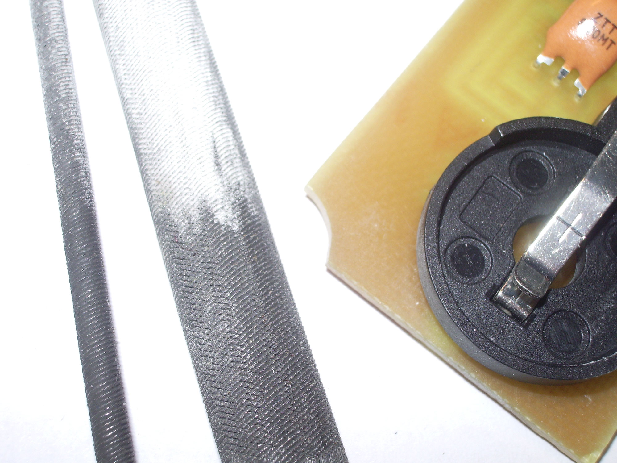
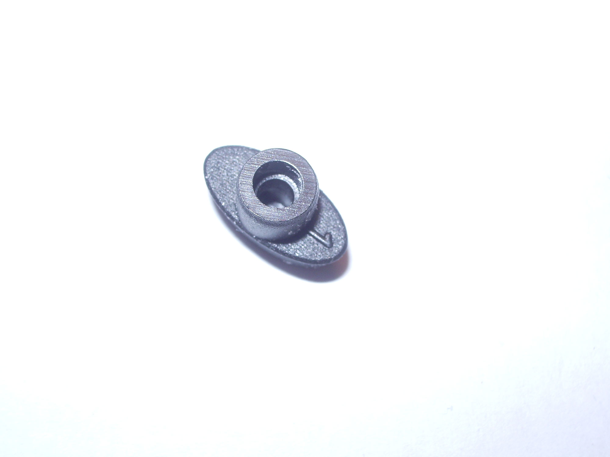
In the case some holder elements have to be cut away. (marked in red) The rounding on the PCB is filed with a key file. For the LED holes, a small round key file is best.
I had to fill the holes in the buttons with hot glue and file them down a bit to get the best fit when the case is closed.
Now have fun with the rebuild!
Downloads
- PCB layout as Target file
- Circuit diagram, assembly diagram
- Firmware with European remote control codes
- Parts list