
Z5700M Nixie Clock
Microcontroller-controlled clock with four vintage RFT Z5700M / Z570M Nixie tubes
I’ve always wanted to design my own Nixie clock. These display tubes were very common in the 1960s and 1970s, even before vacuum fluorescent displays and LEDs became available. The operating principle is similar to that of a neon lamp, but with the anode designed as a metal grid on the front. The digits 0-9 are formed by metal plates arranged behind the anode, which serve as cathodes and can be individually controlled. The tubes, which are typically filled with neon, operate on a DC voltage of around 180V and produce a beautiful orange-red glow.
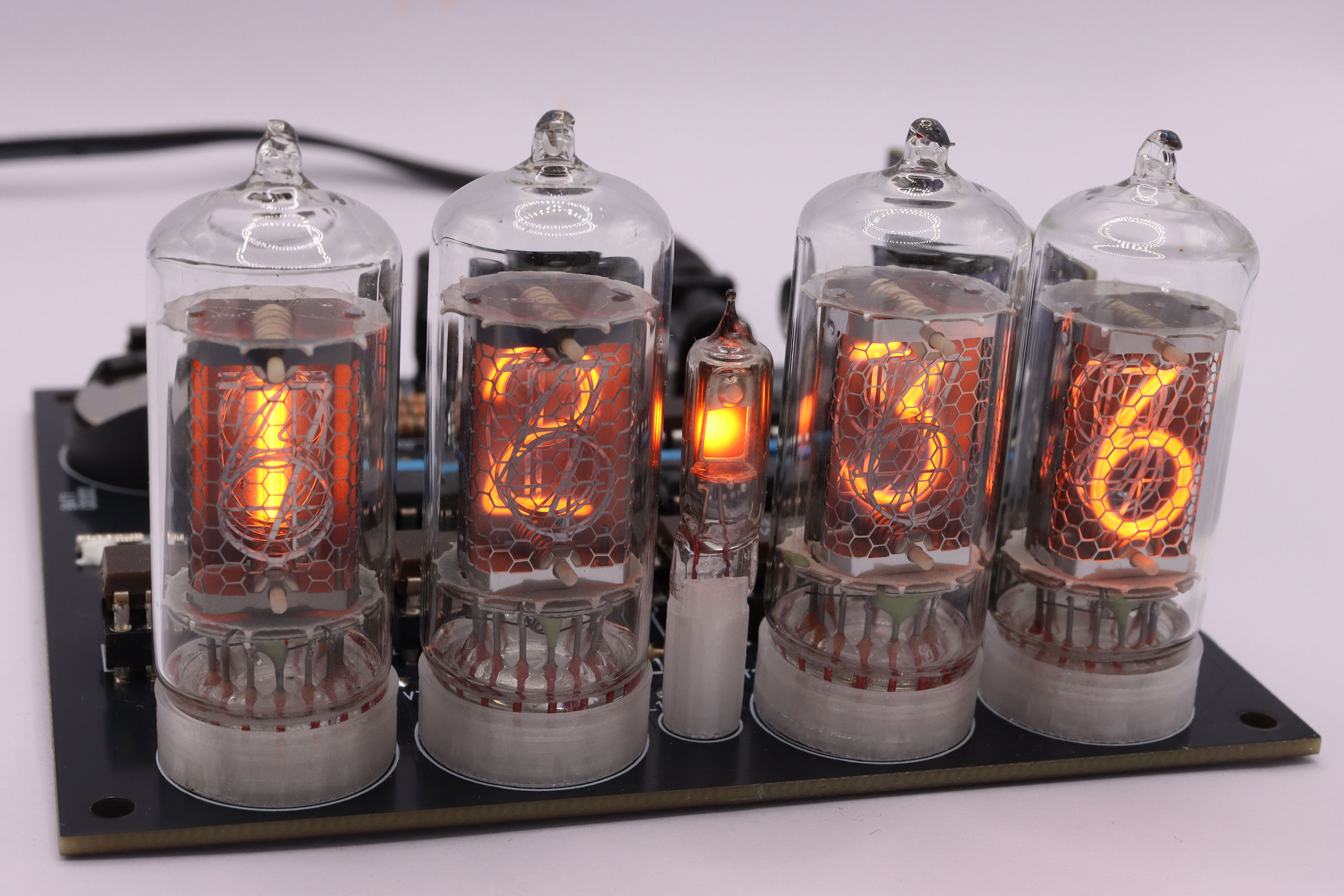
These tubes were manufactured in East Germany by the „Werk für Fernsehelektronik“ (WF), later known as RFT. A whole series of tubes with identical wiring were produced there. The Z5700M is the clear version, while the Z570M is coated with red dip coating. Other models (Z5730M, Z573M, Z5740M, Z574M) have additional decimal points (on the right or left) on an otherwise unused pin. A Russian IN-3 (ИН-3) neon bulb is installed in between the two pairs of tubes. It serves as a separator for hours and minutes. The Nixie tubes and neon bulb are mounted on 3D-printed spacers.
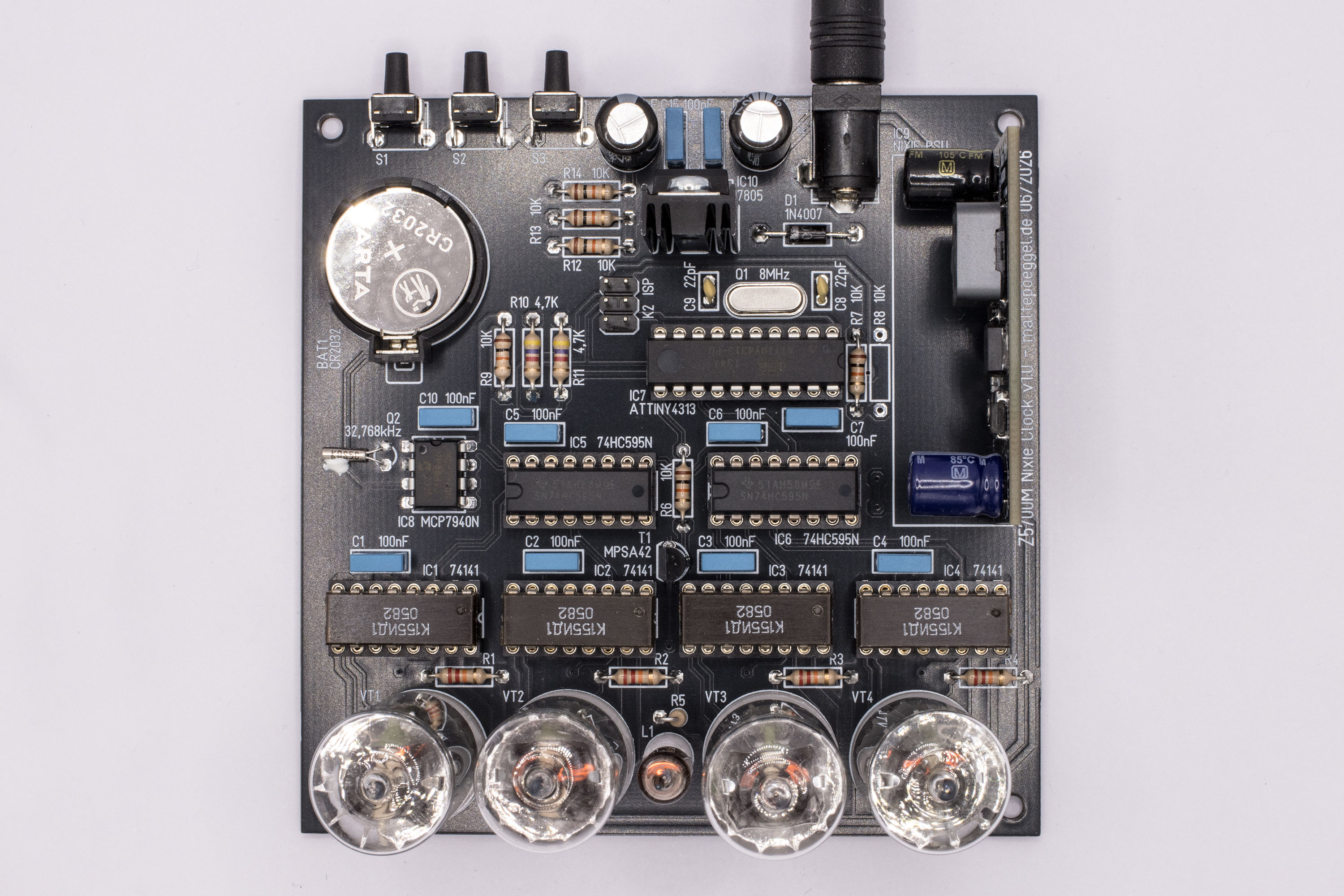
During the development of the circuit board, I paid close attention in order to use almost exclusively through-hole components. To maintain the authentic style, the Nixie driver ICs used are the SN74141 (which were standard at the time) or alternative types such as the K155ID1 (K155ИД1). If these are no longer available, an substitute circuit (linked below) can be used instead.
The high-voltage power supply is designed as a module and soldered vertically onto the main board. Two versions were developed: one using the MC34063 and one using the MAX1771 step-up switching regulator IC. The second is slightly more expensive but operates at a high switching frequency and can be turned on and off via a dedicated pin. In addition to shift registers, an RTC, and a microcontroller, the board features three pushbuttons along the rear edge for setting the time. Power is supplied by an external 12V plug-in power supply.
Circuit description
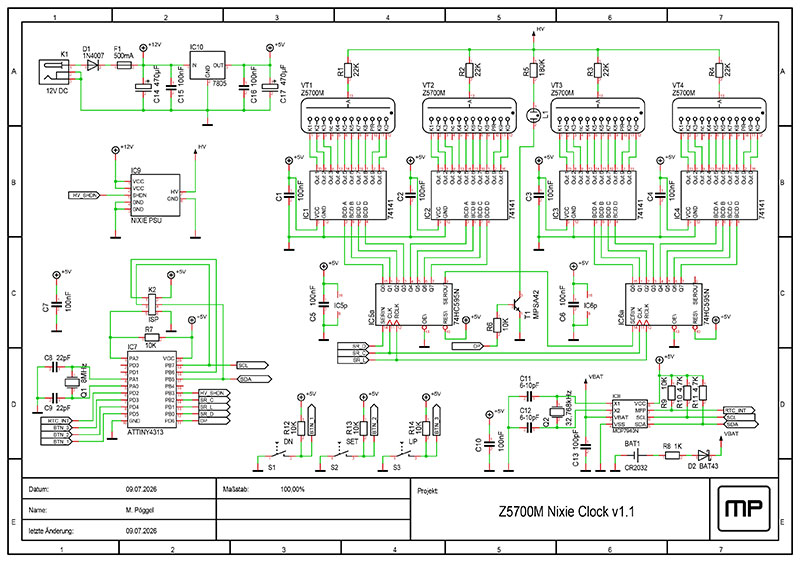
The 5V power supply for the logic ICs is provided by the linear regulator IC10. The diode D1, which provides reverse-polarity protection, and the PTC fuse F1 are connected ahead of it. The 180V high voltage required for the tubes is generated by a specially developed Nixie power supply module, IC9. For the adjustable version, the module must be adjusted externally before final use. The high voltage is supplied to the anodes of the Nixie tubes VT1-VT4 via series resistors R1-R4. The individual digits, along with their respective cathodes, are connected to the SN74141 Nixie driver ICs IC1-IC4. These ICs switch the cathode corresponding to the BCD-encoded digit at the input to ground, thereby igniting the glow discharge in the tube at that cathode. The digit begins to light up. The BCD inputs of all drivers are connected to the shift registers IC5 and IC6. The indicator lamp L1, with its series resistor R5, is switched via transistor T1. The above-mentioned peripherals are connected to the ATTiny4313 microcontroller IC7, which handles the central control. In addition, an 8 MHz crystal Q1, along with the capacitors C8 and C9 required for the resonant circuit, three pushbuttons S1-S3 with their associated pull-up resistors R12-R14, and an MCP7940N real-time clock (IC8) are connected to it. The pull-up resistors R9-R11 are required for the RTC’s pulse output and the I2C bus. The 32 kHz oscillator consists of the crystal Q2 and capacitors C11 and C12. The RTC continues to run from the CR2032 button cell BAT1 in the event of a power failure. The manufacturer recommends diode D2 and resistor R8 as additional protection against charging the button cell.
Firmware
The firmware uses the PlatformIO build environment with the AVR-GCC toolchain and has no other dependencies. To use it in the console, download PlatformIO Core; alternatively, you can use VS Code with PlatformIO as a plugin as IDE.
After downloading the firmware from GitHub, navigate to the corresponding directory in the console.
cd nixieclock-z5700m
To program the ATTiny4313, you'll need an AVR-ISP (e.g., USBasp) with a 6-pin connector. This is connected to the ISP connector K2. In addition, the assembled board must be connected to the power supply. Then, the fuse bits are set (once):
Next, the firmware is compiled and uploaded to the controller:
If everything went well, the high voltage should now be activated, and the Nixie tubes should start to light up.
Operating Instructions
The time is set using the three buttons on the back. The functions are as follows: S1: Minus, S2: Set / Confirm, S3: Plus.
If the time has not yet been set, all tubes will flash, displaying 00:00. The setup process is started by short pressing S2. The hour display flashes, and the desired hour can be set using S1 and S3. To skip forward quickly, the buttons can also be held down. Then press S2 to confirm, and repeat this process for the minutes. After pressing S2 again, the time is written to the RTC chip and the clock starts running. If you need to set the time again, you can return to setup mode at any time by holding down S2 briefly.
Operation
Every 10 minutes, the clock runs a routine to prevent „cathode poisoning“ in order to extend the life of the tubes. This can occur when a tube displays the same digit for too long. During this process, non-conductive material is sputtered from the active cathode onto surrounding, inactive cathodes. Less frequently used digits may later light up incompletely. The software therefore cycles through all digits multiple times to prevent this problem.
Enclosure
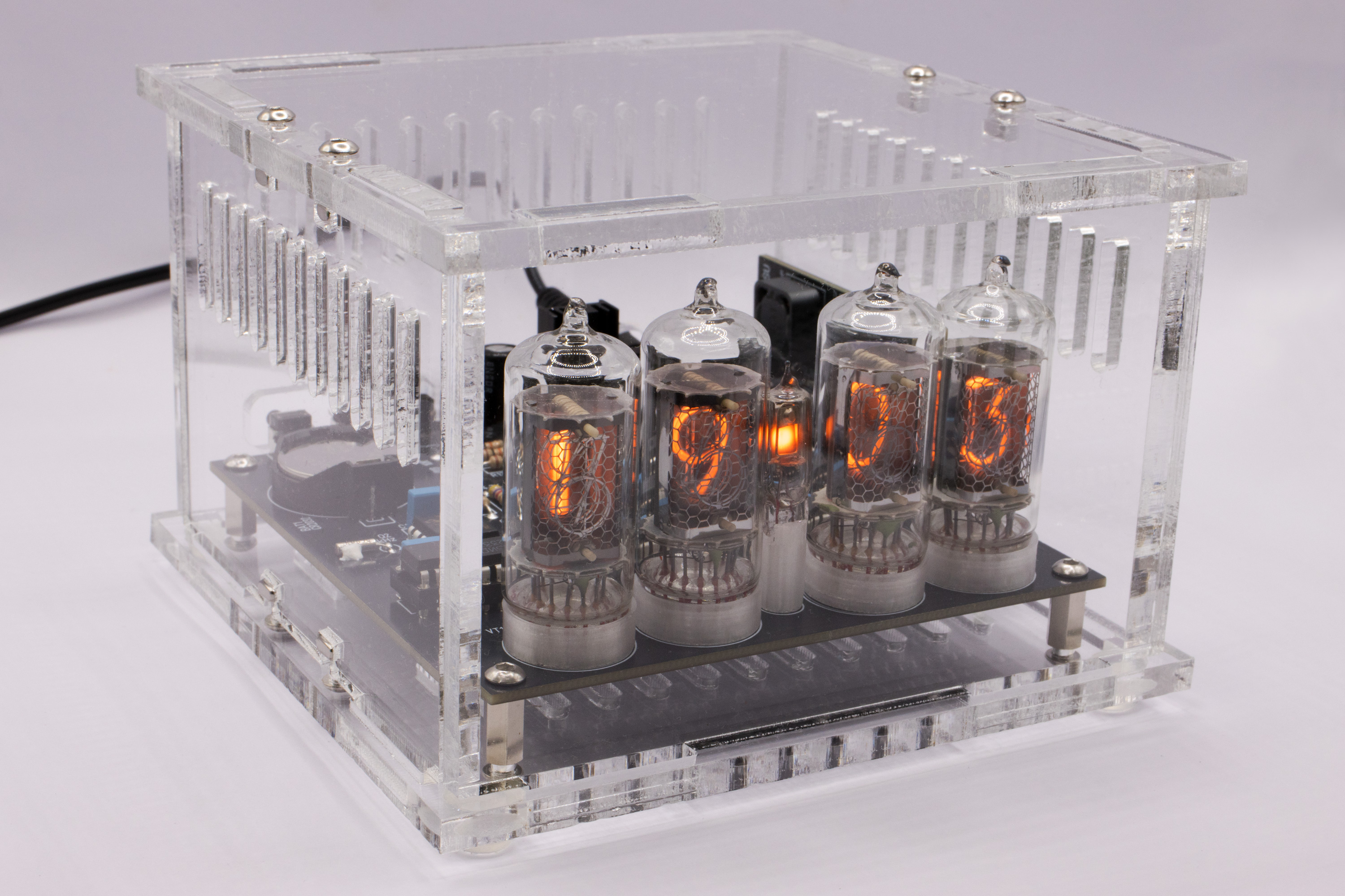
The housing is laser-cut from 5mm acrylic glass. The panels are interlocked and secured using M3 screws and square nuts. The buttons on the back are operated by 3D-printed knobs. Alternatively, buttons with long actuators can be used, but care must be taken when disassembling and reassembling the housing, as these can break off against the snap-fit back panel. Ventilation slots in the bottom and side panels ensure proper air circulation.
Project status
The project is not finished yet, component values may still change.
Links
- tube-tester.com - Nixie Tube Data Archive
- tube-tester.com - Cathode Poisoning Reversal
- threeneurons.wordpress.com - Nixie Stuff
- github.com - Gloeidraad - SN74141 Substitution
Downloads
- Schematic (PDF)
- Bill of material (PDF)
- Layout and BOM
- Layout in Gerber format
- Firmware (GitHub)
- Design files for acrylic case (SVG, DXF)
- Spacer for Z5700M Nixie Tube (Thingiverse)
- Spacer for IN-3 Neon Bulb (Thingiverse)
- Design file for the knob used to extend push buttons with a short lever
License
The project may be used freely for private use, but the author's name must remain on it (CC BY-NC-SA).