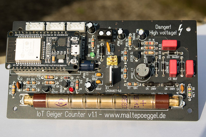
IoT Geiger Counter
Geiger-Müller Zähler mit WLAN / LoRaWAN Anbindung
Vor kurzem erreichte mich eine Frage, welcher Geigerzähler am besten als Strahlungsmonitor an einer Wetterstation geeignet ist. Bei mir läuft zu diesem Zweck seit einigen Jahren ein uRadmonitor Kit1. Dieser Bausatz ist allerdings aufgrund des LAN Ports nicht besonders flexibel, und die Messwerte können nur über Umwege in einer eigenen, lokalen Datenbank abgelegt werden.
Nach weiterer Recherche im Internet konnte ich keinen geeigneten Bauvorschlag finden, der den Anforderungen eines fest verbauten Gerätes als Basis einer drahtlosen Wetterstation gerecht wurde. Eine neue Projektidee war gefunden.
Vor einigen Jahren hatte ich bereits einen Prototyp einer Schaltung mit SBM-20 Zählrohr aus dem Mikrocontroller.net Forum aufgebaut, siehe YouTube Video. Sie stammt von dem User "kolisson". Der Vorteil dieser Schaltung ist die Verwendung von Standardbauteilen sowie die sehr geringe Ruhestromaufnahme. Der Aufbau ist als selbstschwingender Aufwärts-Schaltregler mit nachgeschalteter Villard-Vervielfacherschaltung realisiert. Die Einstellung der Ausgangsspannung erfolgt über Zenerdioden.
Schaltungsbeschreibung
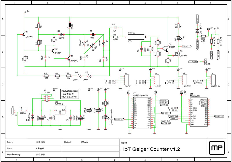
Die Transistoren T2 und T3 bilden den Sperrschwinger, der die Speicherdrossel L1 lädt. Mit der nachgeschalteten Kaskade wird so die von der Spule induzierte Spannung vervielfacht. Sobald die Spannung an C4 die mit den Zenerdioden eingestellte Anodenspannung von 400V erreicht, schalten diese über den Transistor T1 den Schwingkreis ab. Der Anodenwiderstand R8 begrenzt den Strom durch das Zählrohr. Der darüber geschaltete 1pF Kondensator C5 ist ein Vorschlag zur Verbesserung der Plateau-Eigenschaften, kann aber nach Belieben entfallen.
Die 10nF Kondensatoren C2, C3, C4 in der Kaskade sind mit 630V spezifiziert. In Tests hat sich die WIMA MKP10 Serie durch ihre geringen Verluste als optimal erwiesen. Die Keramikkondensatoren C5 und C6 sollten eine Spannungsfestigkeit von 500V haben. Außerdem ist die Auswahl der Zenerdioden kritisch. Auch hier spielt der Leckstrom eine große Rolle. Je nach Typ wird die Hochspannung mehr oder weniger genau eingeregelt. Ich habe die Zenerdioden BZT03C200 gewählt. Da diese im Glasgehäuse einen photoelektrischen Effekt aufzuweisen scheinen, empfiehlt es sich die Zenerdioden vor dem Einlöten mit Schrumpfschlauch zu überziehen. Bei den in der Teileliste genannten Alternativen im Plastikgehäuse (u.a. 2EZ200D5) ist dies nicht nötig. Zur Kontrolle der Anodenspannung sollte ein besonders hochohmiges Analogvoltmeter (z.B. Unigor 3n mit 31,6kOhm/V im 1kV Bereich) verwendet werden. Digitale Voltmeter haben meist in allen Bereichen eine Impedanz von 10MOhm, unter der die Hochspannung um einige hundert Volt einbricht. Einige weitere Infos finden sich in diesem Twitter Thread (Archiv Screenshot).
Das Zählrohr SBM-20 stammt aus der Sowjetunion und ist aus Restbeständen leicht zu beschaffen. Alternativ kann das J305βγ (107mm Länge) aus China eingesetzt werden. Beide detektieren Beta- und Gammastrahlen mit vergleichbarer Empfindlichkeit. Wird das Gas im Zählrohr ionisiert, so entlädt sich die Hochspannung über den Spannungsteiler aus R9, R10 und R11. C6 verlängert den dabei entstehenden Impuls. Dieser wird durch den Darlington-Transistor T4 verstärkt, schaltet den Feldeffekttransistor T5, und lässt letztendlich die Leuchtdiode D7 aufblitzen.
Eine digitale Auswertung der Impulse erfolgt wahlweise mit einem ESP32 (WLAN) oder einem Moteino R6 (LoRa). Die Wandlung auf 3,3V Logikpegel geschieht dabei durch geschickte Beschaltung der Shottkydiode D10. Über diese und R14 fließen die 3,3V, sobald der Feldeffekttransistor T5 bei einem Impuls gegen Masse schaltet. Der Ausgang ist somit low-aktiv. Die Eingänge beider Mikrocontroller sind so gewählt, dass interne Timer-Baugruppen als Zähler verwendet werden können. Mehr dazu aber später.
Zur Stromversorgung ist entweder ein DC-DC-Modul oder ein Low-Drop-Spannungsregler (IC1) vorhanden. Dieser erzeugt aus einer Eingangsspannung von 6 bis 26V die nötigen 5V. Sofern bereits eine geregelte 5V Versorgung vorhanden ist, kann der Spannungsregler mit der Steckbrücke J2 überbrückt werden. Die Selbstrückstellsicherung F1 sowie die TVS Diode D8 schützen vor Verpolung und Überspannung.
Über die JST Buchsen J3 bis J6 sind I2C und UART Schnittstellen, jeweils mit 3,3V oder 5V Spannungsversorgung herausgeführt. Hier können zusätzliche Sensoren angeschlossen werden. Auf allen Datenleitungen darf ein Signalpegel von 3,3V nicht überschritten werden.
Aufbau
Bei der Bestückung der Platine sollte mit den kleinsten / flachsten Bauteilen (Widerstände, Dioden, etc) begonnen werden. Besondere Vorsicht ist bei dem Feldeffekttransistor T5 gegeben: Dieser ist empfindlich gegen elektrostatische Aufladungen. Nach der Bestückung muss die Unterseite der Platine mit Isopropylalkohol oder Brennspiritus von Flussmittelresten gereinigt werden, da diese eventuell leitend sein können. Wer möchte, kann den Hochspannungsteil zusätzlich mit Isolationslack (z.B. Plastik 70 von CRC Kontaktchemie) überziehen.
Gehäuse und Montage
Die Abmessungen der Platine sind auf den Einbau in ein IP65 Gehäuse wie zum Beispiel G368 / G258 abgestimmt. Baugleiche Gehäuse mit den Außenabmessungen 160x80x55mm werden von verschiedenen Herstellern angeboten. Wer mehr Platz benötigt, kann alternativ das Gehäuse G369 / G265 mit einer Bauhöhe von 85mm verwenden. Alle Kabel sollten über abgedichtete PG Verschraubungen eingeführt werden. Vor dem Einbau der Platine müssen die beiden unter den Buchsen liegenden Abstandshalter mit einem Bohrer oder Seitenschneider gekürzt werden. Trotz Spritzwasserschutzes ist die Montage an einem geschützten Ort zu bevorzugen. Es außerdem empfehlenswert, ein Druckausgleichselement zu verbauen, da ansonsten Temperaturschwankungen dazu führen können, dass Feuchtigkeit in das Gehäuse gesaugt wird. Zur Sicherheit kann auch ein kleines Päckchen Trockenmittel (Silica-Gel) mit hineingeklebt werden.
Nutzung des ESP32 mit WLAN
Als Software für den ESP32 dient die freie Firmware ESPHome. Mit dieser können ohne Programmierkenntnisse diverse Sensoren integriert und verarbeitet werden. Die Konfiguration der Firmware wird über YAML Dateien vorgenommen.
ESPHome nutzt beim ESP32 automatisch das im Mikrocontroller vorhandene PCNT (Pulse Counter) Modul. Ich habe einige Tests mit einem Funktionsgenerator vorgenommen und war erstaunt von der Genauigkeit der ausgegebenen Werte.
Wer HomeAssistant benutzt, kann die Firmware direkt über die Weboberfläche erzeugen und übertragen. Soll ESPHome mit Hilfe des eigenen PCs aufgespielt werden, wird hierzu Python 3 benötigt. Unter Windows muss dieses zuvor installiert werden, unter Linux ist es bereits vorhanden. Mit dem Befehl "pip3 install esphome" auf der Konsole wird die Installation von ESPHome und allen weiteren Abhängigkeiten gestartet.
Beispielhaft kann nun die Datei geigercounter.yaml mit einem Editor angelegt werden:
name: geigercounter
platform: ESP32
board: esp32doit-devkit-v1
wifi:
ssid: "WLAN-SSID"
password: "WLAN-Password"
i2c:
sda: 21
scl: 22
scan: false
sensor:
- platform: pulse_counter
pin: 14
name: "CPM"
id: "cpm"
on_value:
then:
- component.update: radiation
update_interval: 60s
- platform: template
name: "Radiation"
id: "radiation"
state_class: "measurement"
unit_of_measurement: "uSv/h"
lambda: |-
return (id(cpm).state * 0.00570027);
accuracy_decimals: 3
update_interval: never
# Enable BME280 temperature / humidity / barometric pressure sensor
# - platform: bme280_i2c
# temperature:
# name: "Temperature"
# id: "temperature"
# oversampling: 16x
# humidity:
# name: "Humidity"
# id: "humidity"
# pressure:
# name: "Pressure"
# id: "pressure"
# address: 0x76
# update_interval: 300s
# Enable OLED display
# font:
# - file: "gfonts://Roboto"
# id: roboto
# size: 16
#
# display:
# - platform: ssd1306_i2c
# model: "SSD1306 128x64"
# address: 0x3C
# lambda: |-
# it.printf(0, 0, id(roboto), "R: %.3f uSv/h", id(radiation).state);
# it.printf(0, 16, id(roboto), "T: %.2f °C", id(temperature).state);
# it.printf(0, 32, id(roboto), "H: %.2f %%", id(humidity).state);
# it.printf(0, 48, id(roboto), "P: %.2f hPa", id(pressure).state);
web_server:
port: 80
# Enable MQTT
# mqtt:
# broker: "192.168.0.100"
# username: "MQTT-User"
# password: "MQTT-Password"
# topic_prefix: "MQTT-Topic/geigercounter"
# log_topic:
# discovery: false
# Enable Home Assistant API
# api:
# reboot_timeout: 0s
# Enable logging
logger:
ota:
- platform: esphome
password: "OTA-Password"
Die auskommentierten Zeilen können aktiviert werden, sofern ein BME280 Temperatur-, Luftdruck-, Luftfeuchtesensor oder OLED Display eingesetzt werden soll, oder die Datenübermittlung über MQTT bzw die Home Assistant API gewünscht ist. In jedem Fall können die aktuellen Werte über den Webserver auf dem ESP32 abgerufen werden.
Um das Programm zu compilieren und über USB auf den ESP32 zu übertragen, werden in dem Ordner in dem sich auch das YAML File befindet folgende Befehle ausgeführt:
esphome upload geigercounter.yaml
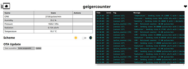
Wenn das Programm nun erfolgreich compiliert und übertragen wurde, ist der Zähler einsatzbereit. Mit einem Webbrowser lässt sich über die vom WLAN-Router zugeteilte IP Adresse die Oberfläche mit den Messwerten ansehen:
Nutzung des Moteino R6 mit LoRa
LoRa Funktechnik kann überall dort eingesetzt werden, wo kein WLAN verfügbar ist und eine hohe Reichweite (1 km) zur Basisstation (Gateway) gefordert wird. Die LoRaWAN-Implementierung unterstützt OTAA und ABP und ist kompatibel mit TheThingsNetwork und ChirpStack. Ein passender JavaScript Payload Decoder ist ebenfalls vorhanden. Durch die relativ geringe Stromaufnahme von etwa 15mA ist auch ein Solar / Batteriebetrieb denkbar.
Der auf dem Moteino verbaute Prozessor ist ein Arduino kompatibler Atmel ATMega328P. Zur einfachen Kompilierung und Inbetriebnahme wird die PlatformIO Toolchain verwendet. Das Projekt nutzt die weit verbreitete MCCI Arduino LMIC-Bibliothek für LoRa. Sobald eine Verbindung zum Netzwerk hergestellt wurde, werden die Sitzungsdaten in einem SPI FRAM gespeichert. Hardware-Timer werden verwendet, um die Impulse des Zählrohres zu zählen und eine Taktquelle für die 60 Sekunden Gate-Zeit bereitzustellen. Da die Übertragungszeit im 868 MHz ISM Band begrenzt ist, werden die Daten in einem 5-Minuten-Intervall gesammelt und ein durchschnittlicher CPM-Wert berechnet und gesendet. Wenn ein BME280 Sensor angeschlossen ist, werden auch Daten zu Temperatur, Luftfeuchtigkeit und Luftdruck übertragen.
Der Quelltext und eine detailliertere Beschreibung finden sich auf GitHub - IoT Geiger Counter LoRaWAN Firmware.
Visualisierung der Daten
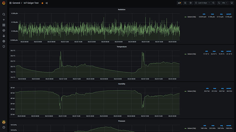
Ich selbst aggregiere sämtliche Sensordaten per MQTT (Mosquitto). Dabei spielt es keine Rolle, ob diese direkt über WLAN, oder über einen beliebigen LoRa Stack eingehen. Der Bridge Modus lässt sogar einen Datenaustausch zwischen verschiedenen MQTT Servern zu. Telegraf schreibt alles gesammelt in eine InfluxDB. Die Messwerte lassen sich anschließend mittels Grafana in einem hübschen Dashboard aufbereiten.
Zum schnellen Einstieg habe ich eine Beispielkonfiguration des Telegraf-InfluxDB-Grafana Stack mittels der Containervirtualisierung Docker vorbereitet, die innerhalb von wenigen Minuten startklar ist. Weiterführende Informationen zur manuellen Installation und Konfiguration finden sich auf den Herstellerseiten sowie in verschiedenen Tutorials.
Als mögliche Alternative zu dieser Konfiguration kann auch HomeAssistant Lovelace oder NodeRed Dashboard verwendet werden.
Umrechnung der CPM Werte
Die gemessenen Impulse pro Minute variieren je nach eingesetztem Zählrohr. Um diese in die Äquivalentdosis, gemessen in Sievert umzurechnen, werden folgende Umrechnungsfaktoren verwendet:
- SBM-20, STS-5:
- CPM/µSv/h: 175,43
- Faktor: 0.00570027
- J305βγ:
- CPM/µSv/h: 123,14709
- Faktor: 0.00812037
Quellen: DIY Geiger - GM Tube Info und de:arduino:radioactivity [OB121]
In Grafana kann der Faktor beispielsweise direkt im SELECT Statement mit der Funktion math(*0.00570027) auf den gemessenen CPM Wert aus der Datenbank angewendet werden.
Bekannte Probleme
- Rote LED leuchtet dauerhaft: Zählrohr defekt, interner Kurzschluss. Bei der Beschaffung von SBM-20 über eBay ist Vorsicht geboten.
Fehlerkorrekturen
- Version 1.0: Prototyp, unveröffentlicht
- Version 1.1: Rastermaß der Hochspannungskondensatoren auf 7,5mm (Wima MKP10) erhöht, verschiedene Isolationsabstände verbessert
- Version 1.2: Rastermaß von C7 auf 3,5mm korrigiert, Zählerimpuls von GPIO12 auf GPIO14 gelegt (Pullup an GPIO12 setzt Flash Parameter im Bootloader, dies kann zu Problemen führen)
Downloads
- Schaltplan (PDF)
- Stückliste (PDF)
- Layout und Stückliste
- Layout im Gerber Format
- Leiterplatte bei Aisler
- Leiterplatte bei OSH Park
- LoRaWAN Firmware auf GitHub
Es sind noch einzelne Platinen und Bauteile aus der Entwicklung übrig. Bei Interesse einfach anschreiben.
Veröffentlichungen
Weitere interessante Projekte
- g3gg0.de IoT Geiger Counter
- AATiS AS622 Geigerzähler
- MightyOhm Geiger Counter
- Ecocurious Multigeiger
- Open Source uRADMonitor KIT1
Lizenz
Das von mir erstellte Platinenlayout darf für privaten Gebrauch frei verwendet werden, der Name des Autors muss darauf jedoch erhalten bleiben (CC BY-NC-SA). Der Schaltplan unterliegt keinen Beschränkungen.


